i have the old linedriver receiver board…ill build the new one from midiphy and try again
i have the old linedriver receiver board…ill build the new one from midiphy and try again
so on the old one this should be already jumpered?
There’s no option to disconnect the +5V on Thorsten’s design.
It’s been a while, sorry. The same jumper is on the Line Transmit board, is it closed? You have the option of external power, as there could be losses through the DB-25 cable.
I’ve added the info for both boards in their respective BOMs. Sorry for any confusion.
hi there thank you it was indeed the jumper on the transmitter…now i have power on the aout board cv, gates and clocks are working !!
another question i have is : is it possilbe to also connect the (old) TPD ?
in my seqv4 i had it after the doutx4… but now i see there is something different in the hw file (the option to choose the midiphy tpd)
now TPD enabled 3 is set…and normally with the seqv4…TPD 2 would be set…would it even be possible to connect the old TPD?
##################################################
##################################################
TPD_ENABLED 3
cheers
Vincent
I’m glad it was something simple.
For the TPD, you can’t display both the Activity Matrix on the JA board and the external TPD matrix. You can probably assign the extra buttons and LEDs/segment displays on the TPD though.
On 3/29/2019 at 5:23 PM, latigid on said:
Let’s see a hi-res photo of the board.
So after giving the board a thorough clean with ISO alcohol in preparation for it’s photo shoot, Ifound a pin on J89 that didn’t look soldered too well, so I reflowed it. It all works now. I am relieved that I don’t have to show you all my crappy soldering.
Good work!
After ~10 years of soldering with a conical 0.5mm tip, I have recently discovered the joy of a 1.6mm chisel tip. It really is night and day with SMT as you get great heat transfer to the flat pads (always heat the pad if possible), then apply 0.5mm solder to the pin et voilà!
With a conical tip I always had to use the side of the iron for SMT and the heating was much more tedious. Still the conical tip is better for larger THT components, pots and jacks etc.
I have both irons at hand and just plug what’s needed into the soldering station ![]()
On 3/26/2019 at 10:02 PM, latigid on said:
I seem to have same problem, running the sdcard command in the MIOS terminal returns:
Quote
[17225.948] Reading Root Directory
[17225.948] ======================
[17225.949] SD Card: not connected
[17225.949] Failed to open root directory - error status: 12
[17225.949] done.
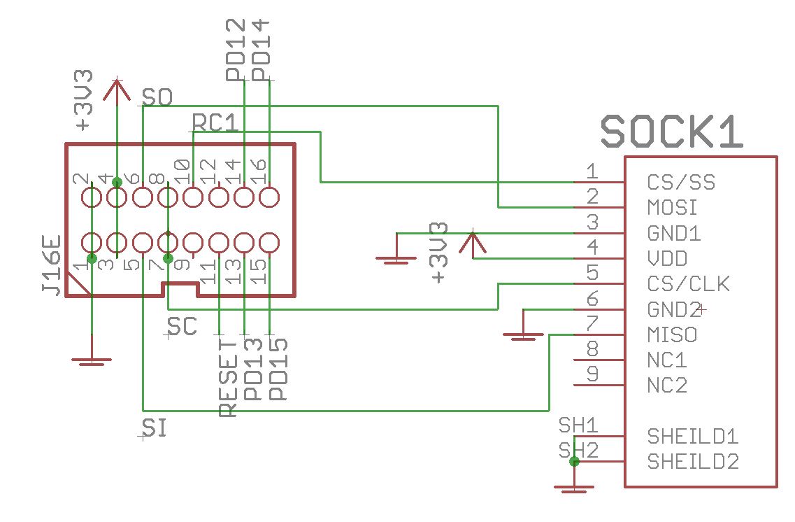
When i check the voltage between Pin 3 GND1 and Pin 4 (VDD) I get a negative voltage, i.e. -3.3V
Black probe to GND1, and Red probe to VDD.
I presume it should not be negative?
Thanks for your time,
Adrian.
Got it! Removed the 3 Jumpers from the Waveshare itself, and changed the slider from USB to 5V and now its working fine!
Peter shows it here at 55:46
https://youtu.be/QaN26uzUA1A?t=3345
On 3/30/2019 at 4:03 AM, latigid on said:
Good work!
After ~10 years of soldering with a conical 0.5mm tip, I have recently discovered the joy of a 1.6mm chisel tip. It really is night and day with SMT as you get great heat transfer to the flat pads (always heat the pad if possible), then apply 0.5mm solder to the pin et voilà!
With a conical tip I always had to use the side of the iron for SMT and the heating was much more tedious. Still the conical tip is better for larger THT components, pots and jacks etc.
I have both irons at hand and just plug what’s needed into the soldering station
I just got a conical tip for my iron after finally wearing out the chisel tip that was on there… I have the opposite experience: I miss my chisel tip for THT! I switched because I thought it would be better for SMT, but maybe that was misguided. Either way I think I’ll go back to chisel here soon.
I wonder if it comes down to what you learned with.
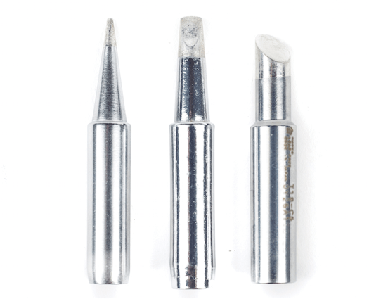
To be clear, I mean one similar to the middle tip of this picture, not the one on the right. It does mean that you have to solder with the iron the same way each time. Maybe my old tip was degraded or my technique wasn’t right, but I never could get things going using the very end of the conical tip, rather I had to use the side.
Yeah I prefer the chisel tip for most things, except for the really small stuff.
On to the next problem, I have moved forward to testing the DINs. Everything works OK…but SW9-12 (Matias) and SW17-20 (MEC).. no response there. I’m guessing it’s one of the 165s? all the soldering on them seems OK.
Any clues where to look?
The tip I had been using was sort of a middle ground between the one of the left and the one in the middle. Definitely a much finer tip than that middle one, but still with a distinct flatted chisel shape. I’m having the same kind of trouble with the new conical tip; it takes a bit more finesse to get it in a position for good heat transfer, but right now I’m only doing THT. Any clever tips (no pun intended) for good technique?
5 hours ago, pat_00 said:
Yeah I prefer the chisel tip for most things, except for the really small stuff.
On to the next problem, I have moved forward to testing the DINs. Everything works OK…but SW9-12 (Matias) and SW17-20 (MEC).. no response there. I’m guessing it’s one of the 165s? all the soldering on them seems OK.
Any clues where to look?
I had this problem too and fixed it by using more tin on the 2 joints on the board. Watch out burning the super leds!
3 hours ago, jaytee said:
The tip I had been using was sort of a middle ground between the one of the left and the one in the middle. Definitely a much finer tip than that middle one, but still with a distinct flatted chisel shape. I’m having the same kind of trouble with the new conical tip; it takes a bit more finesse to get it in a position for good heat transfer, but right now I’m only doing THT. Any clever tips (no pun intended) for good technique?
Gullwing tip and flux pen ftw ![]()
7 hours ago, pat_00 said:
On to the next problem, I have moved forward to testing the DINs. Everything works OK…but SW9-12 (Matias) and SW17-20 (MEC).. no response there. I’m guessing it’s one of the 165s? all the soldering on them seems OK.
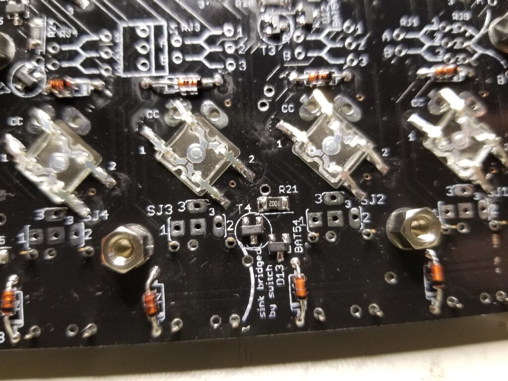
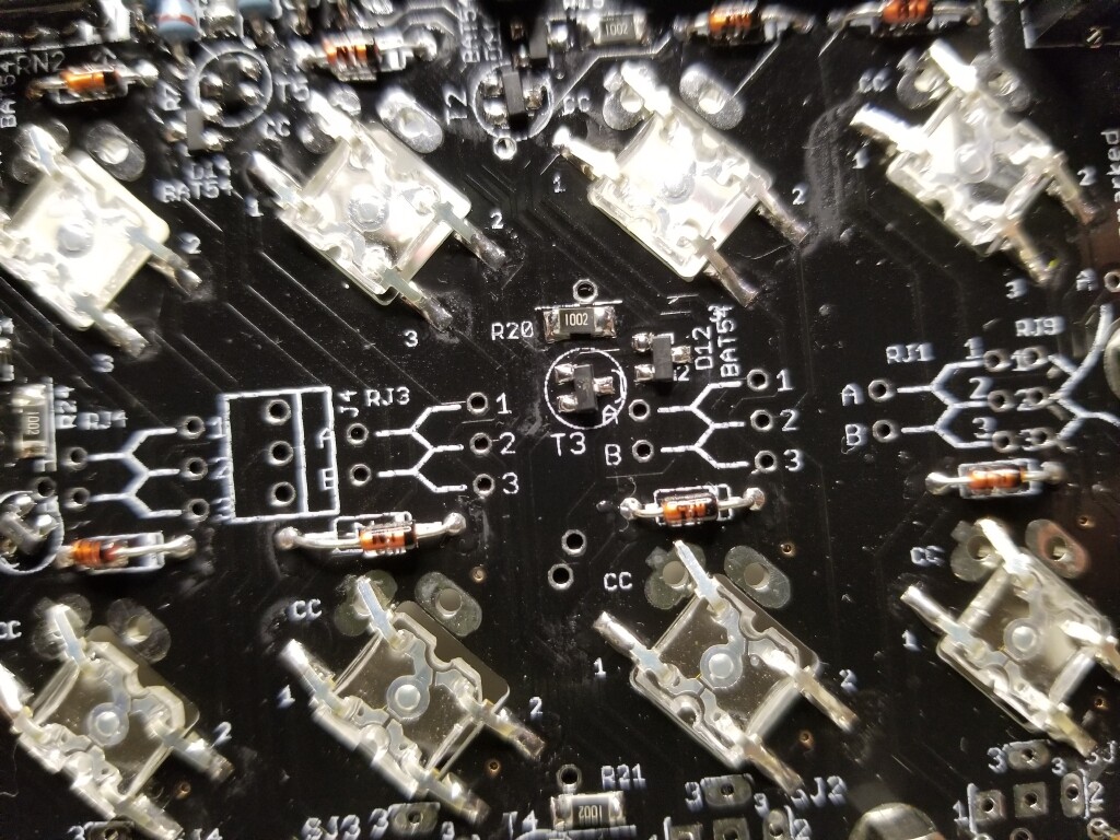
If SW1-4 work, then the problem is on the sink side. Check IC2 and associated resistors T3, T4 and the resistors/diodes adjacent.
Are all diodes soldered with correct polarity?
Please post a picture with your question. It avoids guessing games and is more informative in most cases.
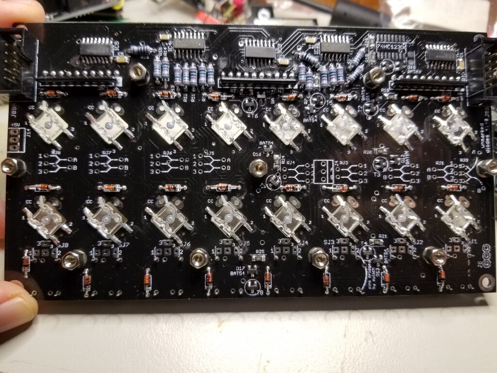
Thanks for the tips, had a look and reflowed a couple of points, but no luck. Here are some pics of the areas you mention and the whole board.
could you try to reupload these pictures? The forum disallows attachments larger than a certain size (i think it is 1MB?), that’s probably why the images come up as broken right now - so you might either need to reduce the JPG quality (not necessarily the resolution) in your image editor before reuploading here or you could upload them as they were on another service (e.g. imgur, dropbox, …)
Thanks and many greets!
Peter
Ok, I re-uploaded them at under 800kb each. Hope that works.