Troubleshooting midiphy SEQ v4+


Yes, you can run it from a good 5V/1A USB supply. I have a USB Power meter (just as posted), and the v4+ current use hovers around 0.5-0.6A during normal use.

On a sidenote, make sure you have a good power supply, if you experience reboots or dropouts, exchange it for another one - i tried to attach one SEQ v4+ and two LoopAs (all have about the same current draw) to a nominally 5V/3A rated PSU on a powered USB hub and experienced reboots - using the power meter i measured it all up and and the 5V rail dropped to 4.5V :slight_smile: - another lesson learned, do not assume the PSU power capabilities label on the backside is correct - my cheap PSU could not even reliably supply 1.5A as indicated by the power meter :).

Many greets,
Peter


Hi Guys,


I am almost finished with building the midiphy but I have a last issue. 

When creating the chain with the 2 boards and the matrix the following happens.

In picture 1 I am creating a chain with the matrix first. then the left board and then the right. Testing with seq_l is perfect

In picture 2 which is the config I need I create a chain with the left board first, then the right board and then the matrix and then I got some weird things like the left board showing all lights and the matrix all lights and the right board does nothing at all. It is stalling all operations and set debug on does not give any input anymore.

Any idea what is going on? 

Many greets,

Niels


Hi Niels,

Good progress so far! You can use the same .NGC for testing everything together. Or if you switch to R, then use seq_r.NGC

https://github.com/midibox/mios32/tree/master/apps/controllers/midibox_ng_v1/cfg/midiphy

Best,
Andy


Hi Andy,

Thanks for the tip. Now i understand where the L stands for in seq_l haha.

Everything works when using the R version. Doing some final testing :wink:

Cheers Niels

Having issue with the SD card - I have Midibox NG v1.036 loaded, it shows up in MIOS Studio. I have an SD card with SEQ_L.NGC inserted but when I try the ‘load seq_l’ command I get this:

Quote

[177771.636] load seq_l
[177774.657] [disk_initialize] error while checking for SD Card (status 0)
[177774.658] [disk_read] error while reading sector 0
[177774.658] [FILE] Failed to open root directory - error status: 1
[177774.658] [disk_initialize] error while checking for SD Card (status 0)
[177774.658] [disk_read] error while reading sector 0
[177774.658] [disk_initialize] error while checking for SD Card (status 0)
[177774.658] [disk_read] error while reading sector 0
[177774.658] [FILE] Failed to open root directory - error status: 1
[177774.659] [disk_initialize] error while checking for SD Card (status 0)
[177774.659] [disk_read] error while reading sector 0
[177774.659] [disk_initialize] error while checking for SD Card (status 0)
[177774.659] [disk_read] error while reading sector 0
[177774.659] [FILE] Failed to open root directory - error status: 1
[177774.659] [disk_initialize] error while checking for SD Card (status 0)
[177774.659] [disk_read] error while reading sector 0
[177774.659] [disk_initialize] error while checking for SD Card (status 0)
[177774.660] [disk_read] error while reading sector 0
[177774.660] [FILE] Failed to open root directory - error status: 1
[177774.660] [disk_initialize] error while checking for SD Card (status 0)
[177774.660] [disk_read] error while reading sector 0
[177774.660] [disk_initialize] error while checking for SD Card (status 0)
[177774.660] [disk_read] error while reading sector 0
[177774.660] [FILE] Failed to open root directory - error status: 1
[177774.666] ERROR: failed to load patch ‘seq_l’ on SD Card (status -1)!
[177774.678] [disk_initialize] error while checking for SD Card (status 0)
[177774.678] [disk_read] error while reading sector 0
[177774.678] [disk_initialize] error while checking for SD Card (status 0)
[177774.678] [disk_read] error while reading sector 0
[177774.678] [FILE] Failed to open root directory - error status: 1
[177774.678] [MBNG_FILE_R] /seq_l.NGR (optional run script) not found

If I restart the core and MIOS studio without an SD card it says SD Card Not Found, so I assume it’s not the cable? I’ll admit the polarity of these IDC cables are giving me confusion for some reason, despite the videos haha. But I think I got that ok.

I’ve tried a bunch of different cards, not sure what to do next. Any idea what I should try next?

Try to format the card, I think FAT8 is the best. Then try again. 

If you’ve used shrouded headers, then the cables will always plug in the same way. When making IDC cables, ensure that the notch/nub points in the same direction relative to the cable strands unless otherwise noted. 

Some SD cards don’t seem to work, e.g. if the size is huge like 32 GB (MIOS will use a very small fraction of that).

1 hour ago, latigid on said:

Try to format the card, I think FAT8 is the best. Then try again. 

Thanks for the ongoing help. Do you know how to format FAT8 on a windows 10 machine? I have been googling but can’t find any program. I did find an older post by TK that says formatting via MIOS Studio is the best method by doing sdcard_format, but it fails with this:

Quote

[23416.084] sdcard_format
[23416.246] ATTENTION: this command will format your SD Card!!!
[23416.246]            ALL DATA WILL BE DELETED FOREVER!!!
[23416.246]            Check the current content with the ‘sdcard’ command
[23416.246]            Create a backup on your computer if necessary!
[23416.246] To start formatting, please enter: sdcard_format yes, I’m sure
[23422.269] sdcard_format yes, I’m sure
[23422.431] Formatting SD Card…
[23422.431] Formatting failed with error code: 12!

If I type just ‘sdcard’ it says Reading CID and CSD failed with status 256.  I’m at a loss, I’ve tried multiple cards and the one I’m currently working with is only 8GB and formatted FAT. The other high capacity ones only let me go as low as FAT32.  Maybe I have a bad component but it is recognizing a card is in there. If I had the cable backwards on one end by accident at some point would that have done some damage somewhere?

If I lay the cable down flat, with the connector holes pointing up, the notches are on the same side of each connector. I assume that’s the right orientation.

Edit - Also just in case it helps, only the green LED has been lighting up. 

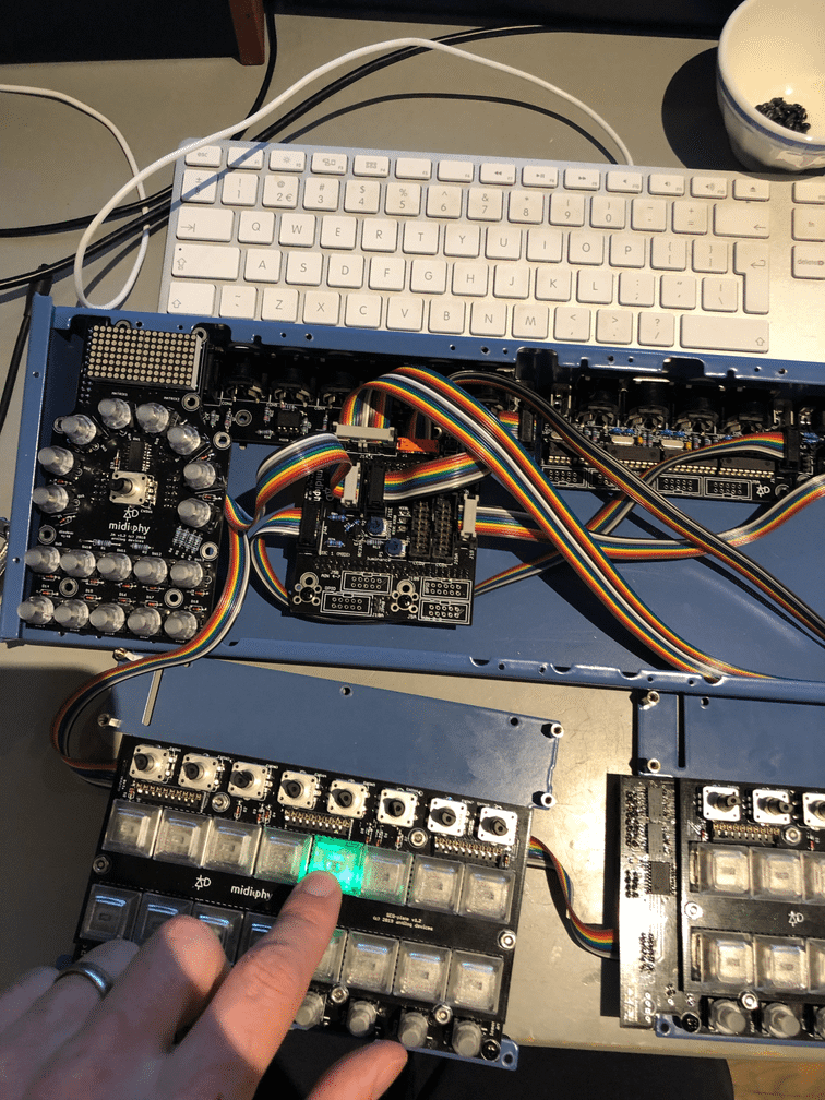
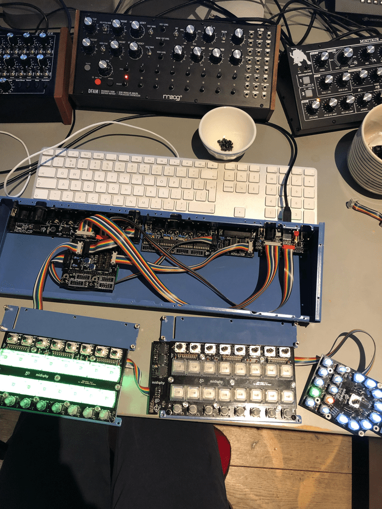
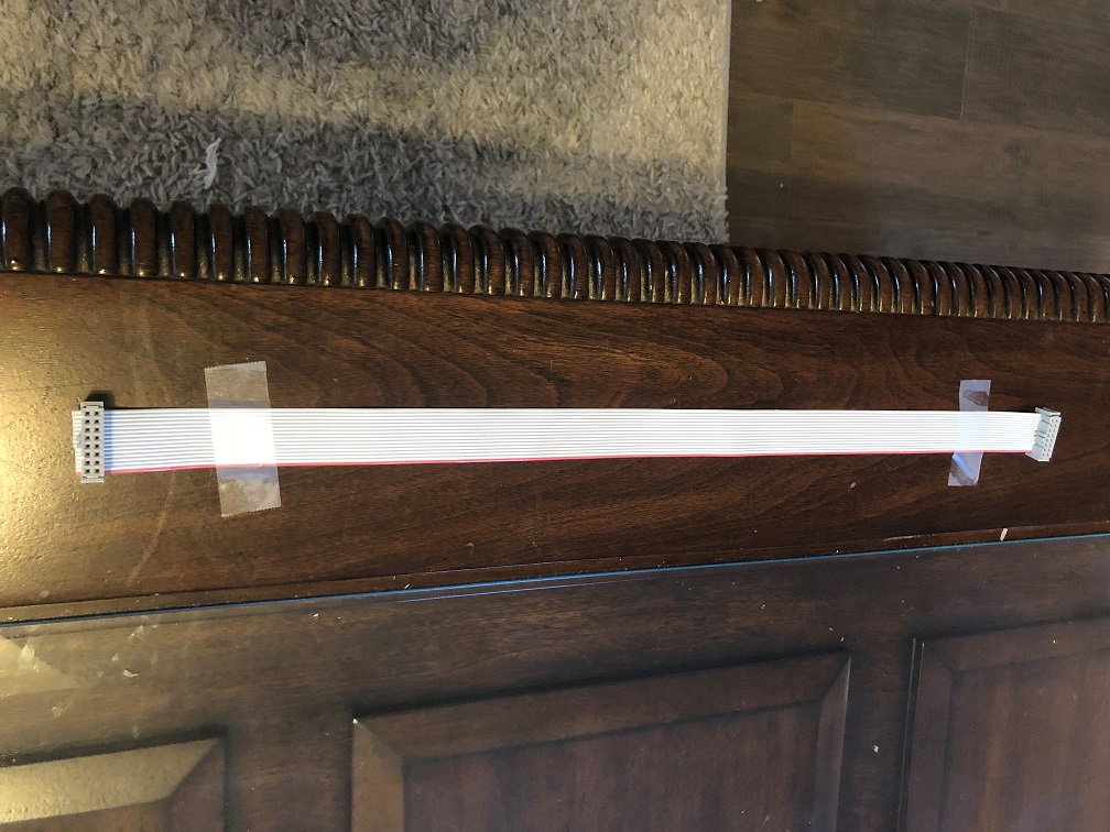
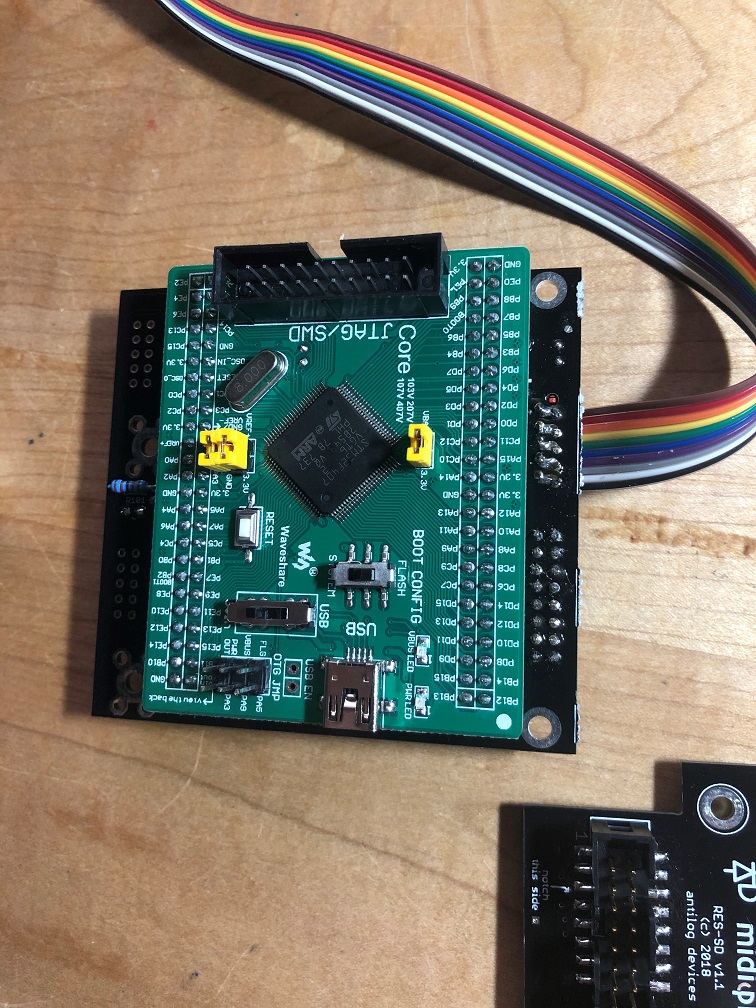
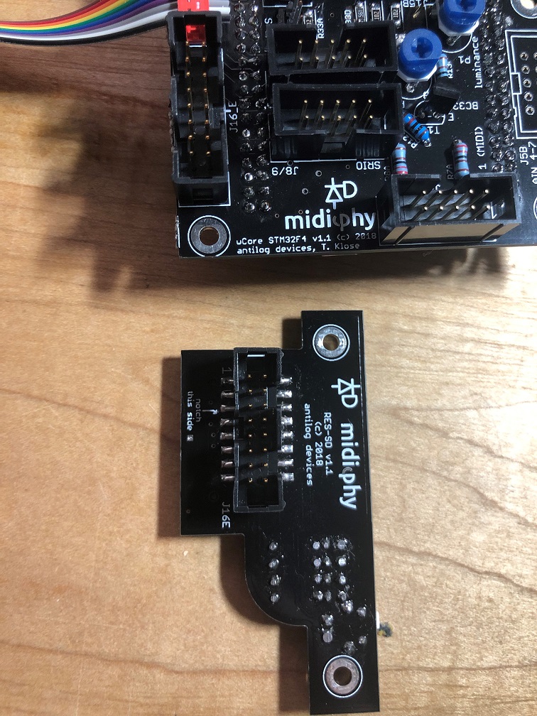
Please provide pictures of the boards, cables and the make/source/sizes of SD cards.

Did you use shrouded headers? If so, you can’t plug the cables in the wrong way, unless they’re incorrectly assembled.


21 hours ago, niles said:

Thanks for the ongoing help. Do you know how to format FAT8 on a windows 10 machine? I have been googling but can’t find any program. I did find an older post by TK that says formatting via MIOS Studio is the best method by doing sdcard_format, but it fails with this:

Try to format using some sort of FAT setting. Is the format successful in Windows?


Quote

If I had the cable backwards on one end by accident at some point would that have done some damage somewhere?

Not seen before, but I guess so? You could’ve damaged the SD card, the MCU pins or both. Again, can you still format the SD cards or are they unresponsive in Windows?


Quote

If I lay the cable down flat, with the connector holes pointing up, the notches are on the same side of each connector. I assume that’s the right orientation.

That’s right, but above you were saying that maybe the cables were backwards? Were they incorrectly assembled before? Shrouded headers or not? See above comments


Quote

Edit - Also just in case it helps, only the green LED has been lighting up. 

J16E carries the LED signals too. If there was a “backwards cable”, then something funny could’ve happend there. But you don’t get many LED signals with _NG. More are active with the SEQ app.


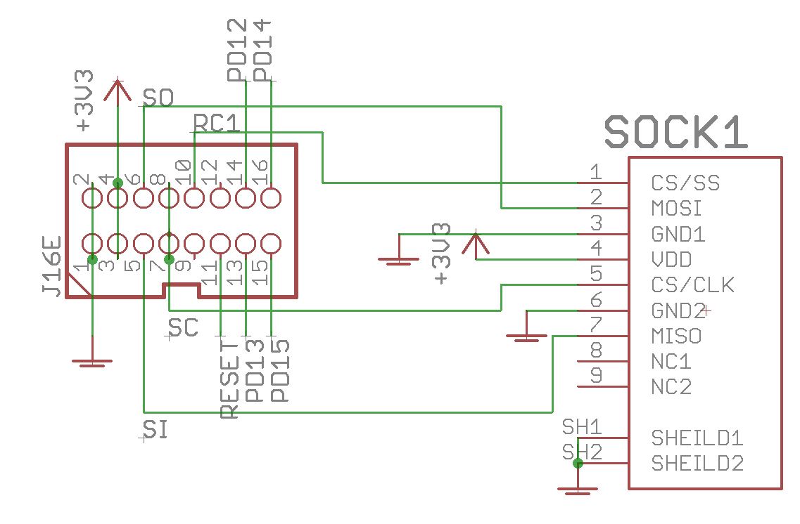
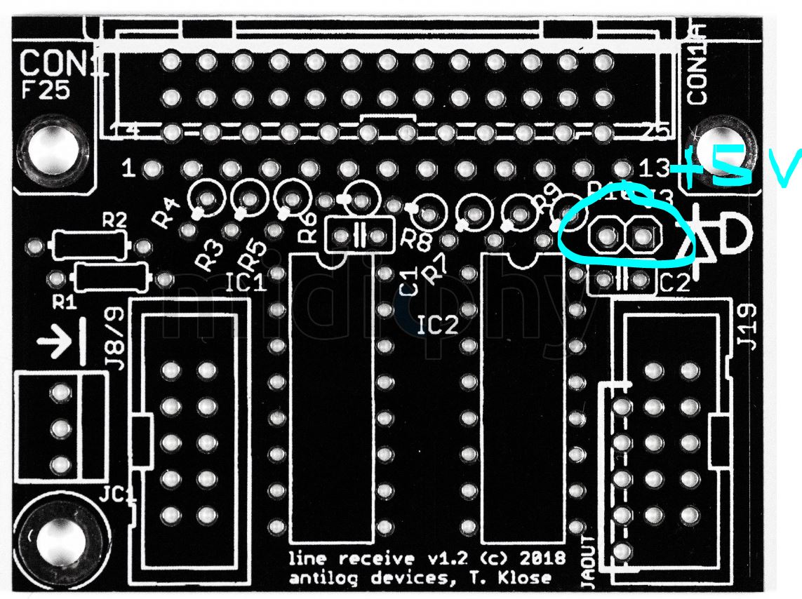
Here’s the schematic. The SD card pinout follows the datasheet that you can get from Mouser.


Check for continuity of pins back to the Waveshare 407v board (with the power off). Check that adjacent pins are not shorted. Make another cable or use the one from an OLED at least temporarily (don’t use the OLED cable!)  You can measure voltage at the SD card. You won’t see much with a multimeter on the other pins, but you can use a scope or logic probe if you have one.

Also, it is possible to overheat these SD sockets. What temperature settings did you use? Were you heating the pins for a long time?


I checked continuity and everything seems fine. The cable is something I did have wrong at first, so perhaps I fried a MCU pin or two. Is there a diagnostic program or command I could run in MIOS Studio that would confirm the pins are 100%?

I’m using shrouded cable sockets and they are oriented correctly I think (please see photos though).

I did order a few more SD sockets (arrow has free one day shipping today :slight_smile: so I’ll replace that just in case. It was simple enough to remove.

The SD cards I’ve tested all format correctly under windows. I found a 32MB one (canon SDC-32M) that is formatted FAT, and a newer 8GB Kingston SDHC (SD4/8GB) that is formatted FAT32. They only contain SEQ_L.NGC , the file from the first post in the seq v4+ thread. Both have the same result. 

The schematic helped, thank you for posting that. Tricky that they put pin 9 out at the end of the SD socket 

Again, thank you for your help with this. I’m obviously hoping it’s not the MCU but I’m not sure what else it could be at this point. Hopefully there’s some kind of test I can run.

6 hours ago, niles said:

I checked continuity and everything seems fine. The cable is something I did have wrong at first, so perhaps I fried a MCU pin or two. Is there a diagnostic program or command I could run in MIOS Studio that would confirm the pins are 100%?

I’m not sure if there’s a tool for SD card diagnostics. There is a dedicated app for a “mass storage device”, but it’s only built for LPC/STM32F1.


6 hours ago, niles said:

I’m using shrouded cable sockets and they are oriented correctly I think (please see photos though).

Sockets look okay


6 hours ago, niles said:

I did order a few more SD sockets (arrow has free one day shipping today :slight_smile: so I’ll replace that just in case. It was simple enough to remove.

Worth a try. Once when soldering a DISCOVERY F4 Core, my sockets were overheated. I don’t know exactly what happened, but the SD card actually overheated and burned up somehow when I inserted it. Take care when soldering the socket. If you can’t manage the smaller pins (in the datasheet they have function names, not pin names) then try leaving them unsoldered. They aren’t connected to the pin header (NC in schem).

It might also be possible to overheat when soldering down the IDC shrouded header.

6 hours ago, niles said:

The SD cards I’ve tested all format correctly under windows. I found a 32MB one (canon SDC-32M) that is formatted FAT, and a newer 8GB Kingston SDHC (SD4/8GB) that is formatted FAT32. They only contain SEQ_L.NGC , the file from the first post in the seq v4+ thread. Both have the same result.

The 32MB would be perfect! It might be useful to have a blacklist/whitelist of SD cards. At the moment I think mine are 4 GB, not sure of the speed.


6 hours ago, niles said:

The cable is assembled correctly but the leftmost socket might be skewed (or the cable was cut on an angle or it’s an unhelpful camera angle). Check for shorts on the cable (e.g. by plugging into the sockets). Note that some pins are intentionally doubled up (see schematic).


quick question related to the pins. I am trying to trace shorts even further and RC1 (pin 10 on the J16), which goes to CS/SS (Pin 1 on SD socket). It’s is the PB2 also called “BOOT1” on the MCU board. Disconnecting the MCU board it’s shorted to ground, is that intended or accidental short? Thanks

I fear I may just have to shell out for a new MCU board, not sure what else to try. Perhaps I can use the original board in another Midibox project in the future without an SD card lol.


Seems to be intended: there’s a BOOT1 solder jumper on the rear bridged to 0V.

407v schem is here

https://www.waveshare.com/w/upload/5/58/CorexxxV-Schematic.pdf

Could be worth doing some pin tracing.

Well there’s no shorts and I don’t know what to do with that schematic anyway. I’ve built plenty of synth-related items but none that rely on SD cards.  I’m at a total loss. It’s too bad there’s no way to just run some kind of diagnostic program that would tell me there’s no input or output received or something. I don’t know enough about how this MIOS studio works to debug errors. 


On 2/6/2019 at 6:46 PM, Hawkeye said:


Are the full schematics available anywhere? I’ve searched online and can’t find them.

I have a problem with testing the JA PCB.

I’ve flashed the NG firmware and the seq_l script loads OK, I set debug on but there is no response from any of the controls or LEDs on the JA board. Any pointers as to where to look?

I have checked all the ICs on the wCore and JA PCBs and reflowed anything that looked less than optimal.


5 hours ago, pat_00 said:

I’ve flashed the NG firmware and the seq_l script loads OK, I set debug on but there is no response from any of the controls or LEDs on the JA board. Any pointers as to where to look?

Let’s see a hi-res photo of the board.

hey there…im trying to get my aout-ng gates and clocks working…

ive set the shift registers in the hw file (10 and 11) but no gates clocks and no cv…also the power led on the aout-ng does not light up with the seqv4+

(and it does light up with my seqv4)

tips are welcome…

cheers

Vincent

Just now, electrodancer said:

ive set the shift registers in the hw file (10 and 11) but no gates clocks and no cv…also the power led on the aout-ng does not light up

Not a good sign. How is the AOUT_NG being powered? There’s an extra jumper on the midiphy Line Receiver that connects to the +5V buss. Is it closed?

Wrong cabling? Let’s see a photo of your setup. What Line Driver boards were you using for the older SEQ?


my setup now is : seqv4+ with new lindriver transmitter but on the other end i have the old linedriver receiver

that might be the problem

aout-ng is powered from my eurorack +12 and -12 volt and it needs power from the sirio chain (i think)


also using the new lindriver transmitter… and the old linedriver receiver board


Old receiver lacks this one, otherwise it’s functionally the same.

1 Like