Thank you - I wasn’t sure how much of that cable I’d need for this kit and was hesitant to tear it apart.
welcome to MIDIbox!
For the Core kit, you will need pieces of 10cm, 20cm, 30cm and 40cm of 10-pin ribbon wire. (Core to MIDI8, LineTX, I2C and USB)
For the Core kit, you will need 40cm of 16-pin ribbon wire (Core to SD Card)
For the UI kit, you will need 7.5cm, 10cm and 2x20cm of 10-pin ribbon wire (SRIO bus through LeMECs, JA and LineTX)
For the UI kit, you will need 25cm and 30cm of 16-pin ribbon wire (2x OLED Displays)
And you need a 35cm split 16/8 pin ribbon wire (requiring 24 pins) to connect the new Activity Matrix displays (on JA) to LeMEC R.
@gotkovsky - the waveshare board should be pushed onto the wCore PCB headers, so that the distance of the wCore underside is not more than 20mm (it needs to be installed on 20mm hex spacers in the case). If you don’t manage to see the MIDI ports in MacOS, could you send us high-res photos of front and backside of the wCore PCB, so that we could have a look?
As i saw, Andy was a bit quicker answering, he is younger and faster, hehe! Have a great weekend y’all!
Many greets,
Peter
Did you use the drop-down menu to select a MIDI port?
Check all jumper settings and try to use the onboard USB micro to connect to your computer.
Yes, no other options than << none >> on the dropdown menu. I also tried with the micro USB, the Waveshare is still powered (VBUS is lit) but doesn’t show up.
please also read my recommendation above. Another test you could do is pull the waveshare daughterboard off, switch its “powered-by” jumper from 5V in to USB mode and connect it without the wCore to your MAC using a mini USB cable. If that works (which is likely), then the problem is on the wCore somewhere, we’d need said hi-res pics, then.
@gotkovsky - the waveshare board should be pushed onto the wCore PCB headers, so that the distance of the wCore underside is not more than 20mm (it needs to be installed on 20mm hex spacers in the case). If you don’t manage to see the MIDI ports in MacOS, could you send us high-res photos of front and backside of the wCore PCB, so that we could have a look?
Ok, the headers were just not pushed enough, I just gave it a good push and now everything works fine… not the first time that I feel like the dumbest dude on planet earth on this project ;)
I’m surprised about how much force we need to apply on those so-small pieces sometimes. Anyway, thanks latigid on and Peter for the super fast replies as usual, you guys are the best.
I know you got it running (awesome) but in case anyone else has a ‘not found’ issue in MIOS studio, I had the really large USB switch set wrong - the one between OTG and regular USB mode. Once I switched that it showed up fine.
On a side note, I definitely appreciate the multiple, smaller PCBs vs one or two huge ones. I did a NAVA build a year ago and that took seemingly forever and was just too unwieldy.
Lastly, I was able to load the project.hex file posted from Hawkeye in an earlier post, but is there a newer, official build by TK for this? I have been looking and only found the SVN, no idea how to compile..was hoping the latest firmware binary would just be able to download somewhere obvious. I have a ways to go in this build and can only work a little bit at a time so I’m not too worried right now. However, if there is a seq v4+ firmware version specific to this kit, might be helpful if it’s available on the midiphy page. Just a suggestion.
Lastly, I was able to load the project.hex file posted from Hawkeye in an earlier post, but is there a newer, official build by TK for this? I have been looking and only found the SVN, no idea how to compile..was hoping the latest firmware binary would just be able to download somewhere obvious. I have a ways to go in this build and can only work a little bit at a time so I’m not too worried right now. However, if there is a seq v4+ firmware version specific to this kit, might be helpful if it’s available on the midiphy page. Just a suggestion.
The latest official firmware files are available from http://ucapps.de/mios32_download.html. There is also a thread where “pre-releases” are sometimes available:
I would prefer to keep firmware in one location. I added the link to the parent page on midiphy.com, but unfortunately I’m not clever enough to make it clickable. Perhaps Peter can sort it out
I just had weird issues testing LeMec PCBs. Basically, as soon as I ‘set debug on’, MIOS Studio detects erratic button actions, as pasted here:
[84691.903] [MBNG_LCD] no response from CLCD #1.1
[84691.903] [MBNG_LCD] no response from CLCD #2.1
[84691.904] [MBNG_FILE_C] Event Pool Number of Items: 348
[84691.904] [MBNG_FILE_C] Event Pool Allocation: 12250 of 65536 bytes (18%)
[84691.924] Patch 'seq_l' loaded from SD Card!
[84691.932] [MBNG_FILE_R] /seq_l.NGR (optional run script) not found
[84741.581] set debug on
[84741.584] Debug mode turned on
[84741.586] MBNG_DIN_NotifyToggle(69, 0)
[84741.586] No event assigned to BUTTON hw_id=69
[84741.598] MBNG_DIN_NotifyToggle(69, 0)
[84741.598] No event assigned to BUTTON hw_id=69
[84741.608] MBNG_DIN_NotifyToggle(69, 1)
[84741.608] No event assigned to BUTTON hw_id=69
[84741.618] MBNG_DIN_NotifyToggle(69, 0)
[84741.618] No event assigned to BUTTON hw_id=69
[84741.629] MBNG_DIN_NotifyToggle(69, 1)
[84741.629] No event assigned to BUTTON hw_id=69
[84741.639] MBNG_DIN_NotifyToggle(69, 0)
[84741.639] No event assigned to BUTTON hw_id=69
[84741.651] MBNG_DIN_NotifyToggle(69, 0)
[84741.651] No event assigned to BUTTON hw_id=69
[84741.661] MBNG_DIN_NotifyToggle(69, 1)
[84741.661] No event assigned to BUTTON hw_id=69
[84741.671] MBNG_DIN_NotifyToggle(69, 0)
[84741.671] No event assigned to BUTTON hw_id=69
[84741.682] MBNG_DIN_NotifyToggle(69, 1)
[84741.682] No event assigned to BUTTON hw_id=69
I didn’t include everything as the data flow seems infinite, sorry for the long scroll, I don’t know how to make this as expandable text.
So I took apart the PCBs, inspected everything, reflowed all the joints, but that didn’t change anything. Should also say that JA PCB works fine and has been tested as shown in Peter’s video tutorial.
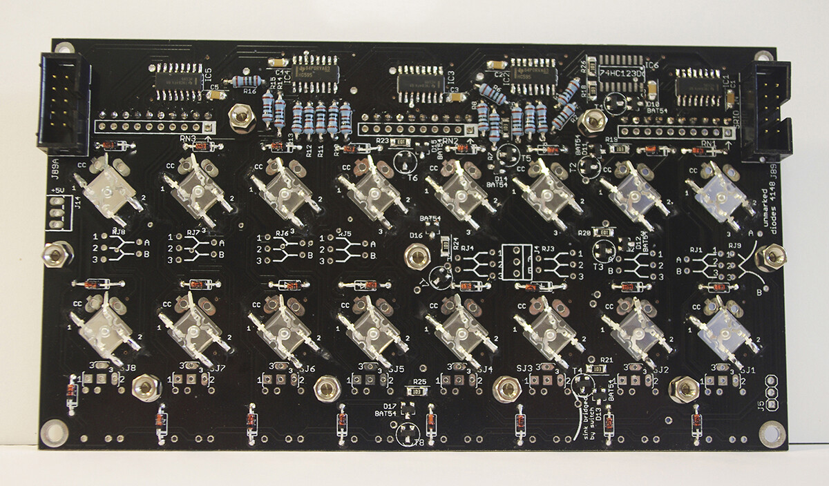
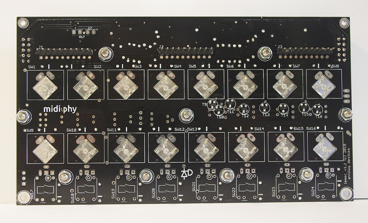
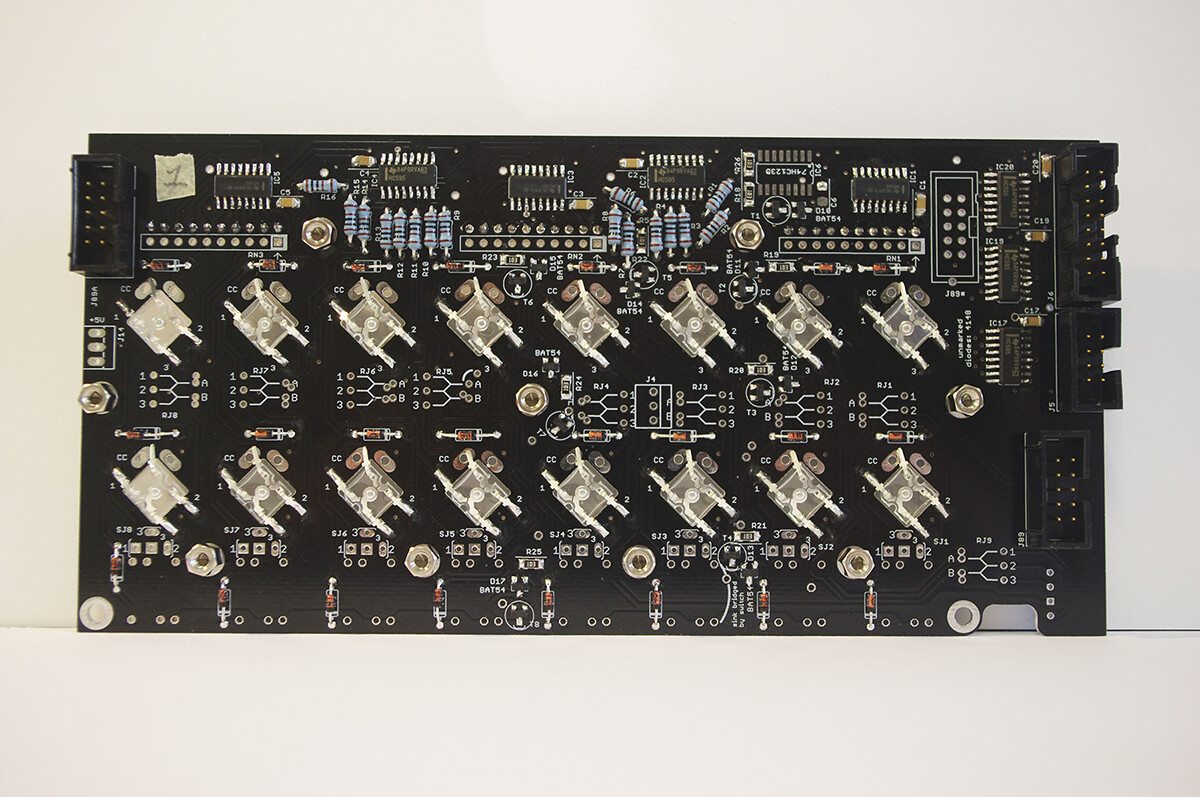
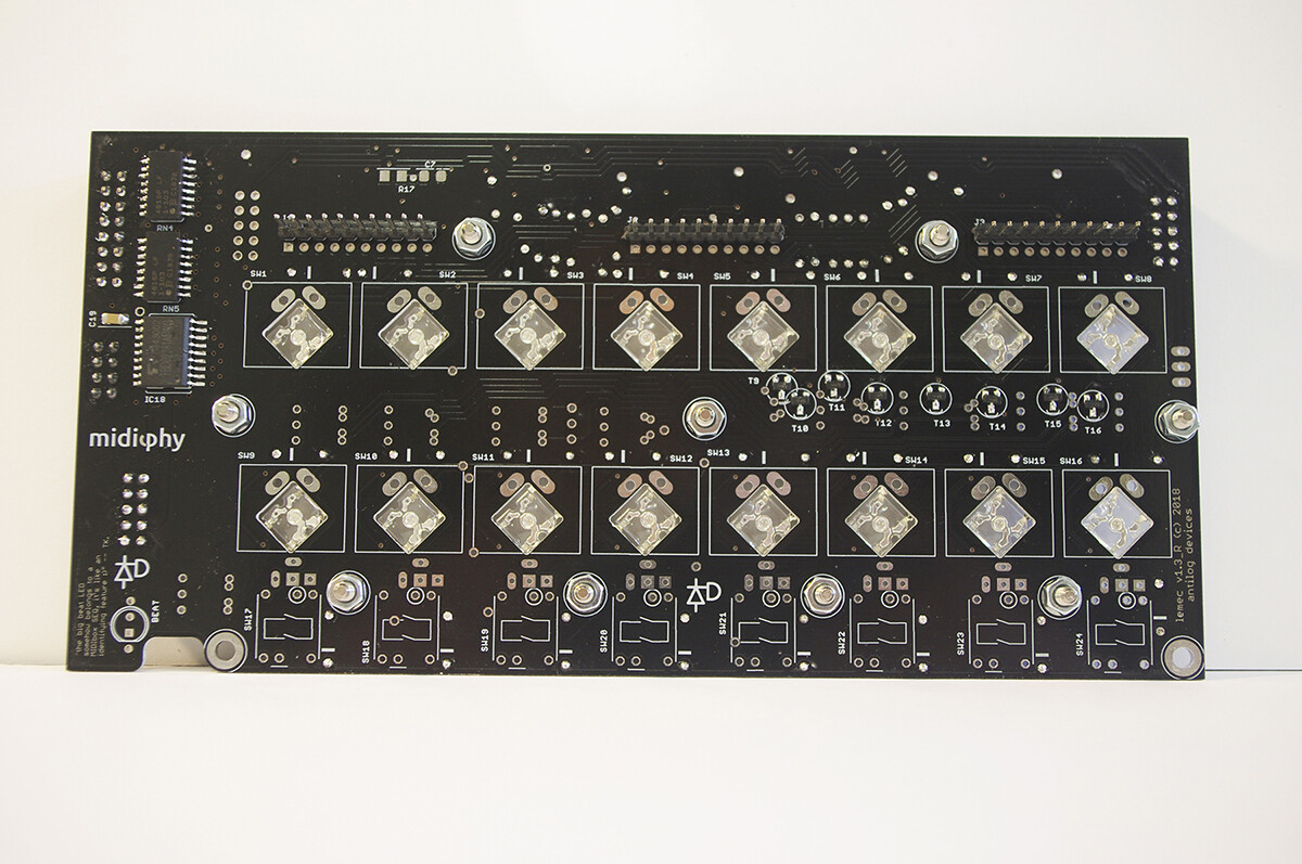
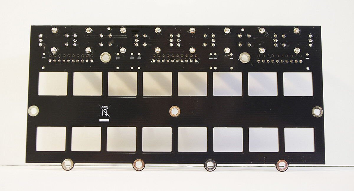
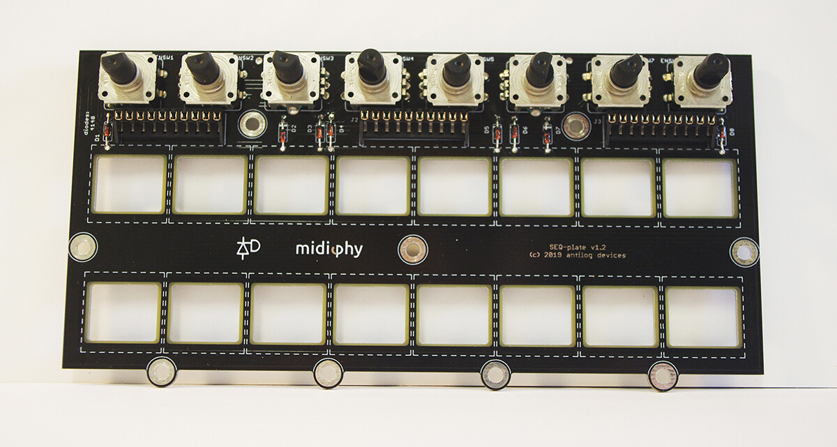
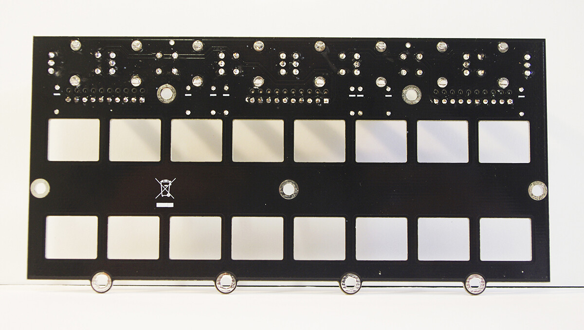
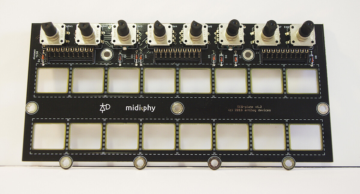
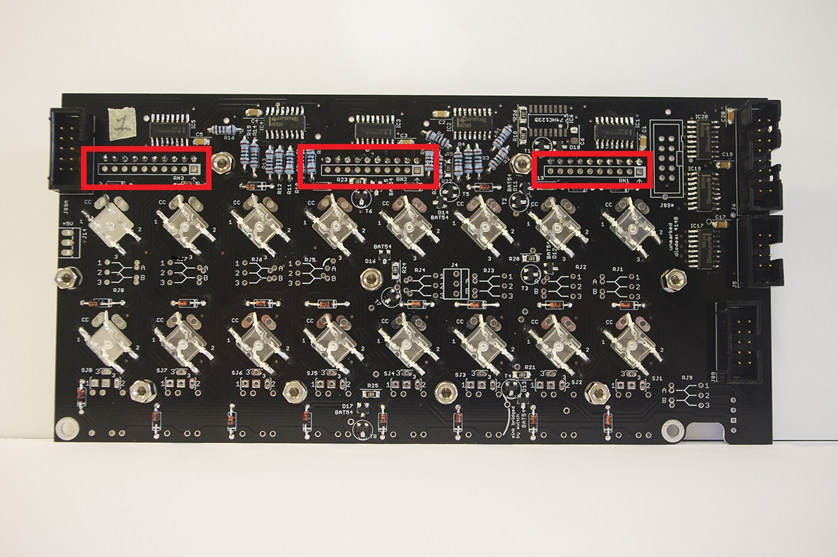
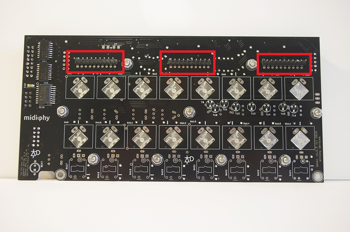
I’m pretty sure your problem is that these parts are not installed. Make sure that you do have bussed resistor networks (9 resistors, not 5 resistors) and align the dot with the marking on the PCB (ask if you are unsure).
No problem. From your SMT soldering and parts placement it looks like you’ve taken a lot of care with the build. Some of the THT pins look like they might benefit from a bit more solder, so make sure you have a proper solder filet from the pad to the pin. Could be the light/angle of the photo though.
No problem. From your SMT soldering and parts placement it looks like you’ve taken a lot of care with the build. Some of the THT pins look like they might benefit from a bit more solder, so make sure you have a proper solder filet from the pad to the pin. Could be the light/angle of the photo though.
I’m coming close to an end on the V4+ build, and just had a question regarding its power requirements.
I’d like to power the SEQ without any computer, using the USB hub and a regular 5V/1A phone USB plug, if possible. I’ve read on the forum that MBSEQV4 power comsuption doesn’t exceed 1A, is that still the same with the V4+?
Also, in the tutorial video (that I’m following closely), Peter says at 2:11:55 to jumper J15_S on the wCore PCB to 3.3V. Should I still do that if I power my V4+ with a 5V phone adapter? Or should I jumper J15_S to 5V?
Also, in the tutorial video (that I’m following closely), Peter says at 2:11:55 to jumper J15_S on the wCore PCB to 3.3V. Should I still do that if I power my V4+ with a 5V phone adapter? Or should I jumper J15_S to 5V?
J15 sets the OLED voltage, which should always be 3v3.
1 hour ago, gotkovsky said:
I’m coming close to an end on the V4+ build, and just had a question regarding its power requirements.
I’d like to power the SEQ without any computer, using the USB hub and a regular 5V/1A phone USB plug, if possible. I’ve read on the forum that MBSEQV4 power comsuption doesn’t exceed 1A, is that still the same with the V4+?
54 minutes ago, Smithy said:
Thats a good question actually!
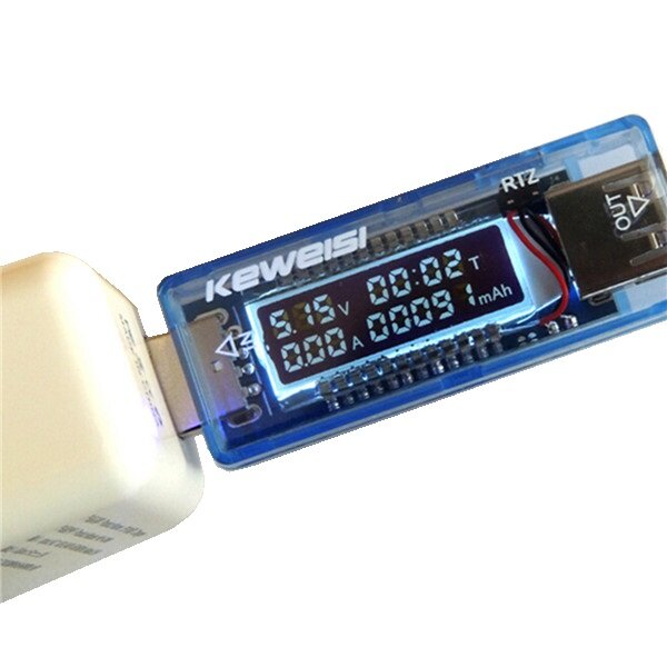
I wonder if Peter or Andy have a USB “doctor” stick to test, they’re really quite handy.
Peter’s done it with a USB power bank. I think the total draw was 0.8A or less, but best for Peter to check in.
if you don’t have access to a hot air rework station (which would be the recommended way to do it), you could try to clip off pin by pin with very fine pincers and then desolder/drag away the pin remains with your soldering iron. This obviously destroys the ICs, but should not be too stressful for the PCB. But as Andy wrote, hot air desoldering should minimize the risk to lift any pads - after warming up the target area, the IC should fall right off :).
Many greets and good luck!
Peter
Thanks for the advice!
I replaced them without too much hassle using hot air. Might have slightly damaged pad 1 on IC1A, but it looks OK for now.
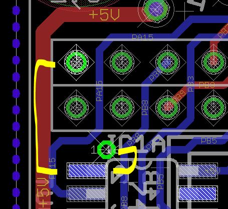
If you don’t measure continuity from 0V (ground) to the pin, you can run a bodge wire as shown. This is viewed from the rear of the board. The via is tented, so the pin on the 2x25 header might be better, but you’ll have to go around to the other side of the PCB (the headers are on the same side as the IC).