13 minutes ago, Hawkeye said:
As you heard my grumbling passage in the video tutorial “i should really get a mac”
I use both OS, It’s less under mac but it also happens ![]()
13 minutes ago, Hawkeye said:
As you heard my grumbling passage in the video tutorial “i should really get a mac”
I use both OS, It’s less under mac but it also happens ![]()
1 hour ago, Hawkeye said:
Congrats on getting it working again! As you heard my grumbling passage in the video tutorial “i should really get a mac” - really meant that at that time, as Windows seems to have quite buggy MIDI-USB. Restarting MIOS Studio or even Windows can help quite often.
Many greets and have fun building,
Peter
Hah yes it’s too true, I think I’d been skipping around the build videos so much I’d missed that you had restarted MIOS Studio to get the board showing up. I do actually have an macbook pro for work but it’s a new one with the damn USB-C ports and I have yet to get an adapter.
I got the JA board up and running this morning, all the buttons and encoder seem functional!
The LeMEC boards are a different story:
On the left LeMEC board it seems like all the buttons (encoder press and matias switches) don’t register, turning encoders left and right behaves correctly.
On the right LeMEC board all of the buttons seem to work as expected, turning encoders works on all encoders except on encoder 16.
I haven’t had a chance to dig into troubleshooting as I had to run to work, but if anyone has a guess as to why all the buttons aren’t working on LeMEC_L I can focus my hunt at lunch/this evening. I’ll update with pictures as soon as I’m able. Thanks again!
38 minutes ago, synaptech said:
I got the JA board up and running this morning, all the buttons and encoder seem functional!
Very good!
38 minutes ago, synaptech said:
The LeMEC boards are a different story:
On the left LeMEC board it seems like all the buttons (encoder press and matias switches) don’t register, turning encoders left and right behaves correctly.
At a guess, R26 is missing, or IC6 is installed without R17/C7. Presumably you haven’t tested LED functions yet?
I can provide more help when I see a picture of the board.
38 minutes ago, synaptech said:
On the right LeMEC board all of the buttons seem to work as expected, turning encoders works on all encoders except on encoder 16.
Do the encoder pins contact the pin header below? Try trimming the pins, also isolate with a bit of tape.
2 hours ago, Hawkeye said:
as Windows seems to have quite buggy MIDI-USB.
Hi !
I dont say that as a excuse for Windows but : we have to keep in mind that before and after a firmware update, it is not the same USB device anymore. And MIOS don’t let the old one go, and don’t show the new one. But well, I think a patch to correct this specific usecase will never happen.
2 hours ago, latigid on said:
At a guess, R26 is missing, or IC6 is installed without R17/C7. Presumably you haven’t tested LED functions yet?
I can provide more help when I see a picture of the board.
Do the encoder pins contact the pin header below? Try trimming the pins, also isolate with a bit of tape.
R26 is there, IC6 isn’t installed so I think R17/C7 are ok being missing? I haven’t tested the LED functions yet but have done a test with my multimeter to make sure all the superflux LEDs are still functional.
2 hours ago, latigid on said:
Do the encoder pins contact the pin header below? Try trimming the pins, also isolate with a bit of tape.
I inspected the two LeMEC boards and can’t spot any shorts between the pins, I did trim the pins on the outside edges to avoid shorting against the header.
I also tried swapping the two SEQ_PLATE pcbs to see if it was a problem with the plate board but the behavior was the same so we should be able to rule those out.
Still having errors uploading directly to the forum, so they’re uploaded to an imgur album again: https://imgur.com/a/naVxaRL
Thanks for the help!
Soldering looks clean and it’s correct to omit IC6 and R17/C7.
Software-wise, how are you testing? Are the boards chained left to right or did you test each one separately? Using the _L configuration will not work if the first board is _R as the matrix is offset by three SRs. Hardware ideas: the transistor types are wrong or swapped, mixed up with a BAT diode etc.
For the missing encoder, on lemec with the plate removed, check J3, 8th pin from the left, to pin 5 on IC5, 9th pin to pin 6, respectively. The pins should have +5V on them. If you (carefully) short the pins to 0V, do the encoder/DIN events trigger? If not it could be a cold solder joint or a short to 0V (e.g. IC5, pin 8).
Now connect the plate PCB. You should have continuity back to IC5. If not, check that the pin header makes good contact with the through-board header.
Just now, latigid on said:
Soldering looks clean and it’s correct to omit IC6 and R17/C7.
Software-wise, how are you testing? Are the boards chained left to right or did you test each one separately? Using the _L configuration will not work if the first board is _R as the matrix is offset by three SRs. Hardware ideas: the transistor types are wrong or swapped, mixed up with a BAT diode etc.
For the missing encoder, on lemec with the plate removed, check J3, 8th pin from the left, to pin 5 on IC5, 9th pin to pin 6, respectively. The pins should have +5V on them. If you (carefully) short the pins to 0V, do the encoder/DIN events trigger? If not it could be a cold solder joint or a short to 0V (e.g. IC5, pin 8).
Now connect the plate PCB. You should have continuity back to IC5. If not, check that the pin header makes good contact with the through-board header.
Back at work so I’ll have to follow up on the testing this evening - but for testing I had everything chained JA->lemec_L->lemec_R. Thanks for the quick responses!
one thing that happened once or twice at my side (built 6 lemec boards in total), was that the SMT IC soldering looks good as seen from above, but there was a little gap between IC leg and PCB, which can only seen from the side - no contact on a pin. This can happen when you “push on the IC”, soldering a single leg first and the IC is not completely flat on the PCB.
Therefore, i’d recommend to use a magnifying glass and check the 595s and 165s pin for pin, especially looking at them from the side.
Looking at your pictures, on the LeMEC L, the upper right pins on IC2 might have suffered from such a fate - it should be easily corrected by re-soldering them with a fine tip and a tiny bit of solder.
Many greets,
Peter
Good news, got the encoder working! I had a cold joint on IC5, the pad looked wet but the leg of the IC hadn’t actually gotten any solder on it.
Still stuck on the buttons on LeMEC L, the transistors are all the same type from what I can see (marked with 6G) and the BAT54s (marked with 5A). Is there a specific IC that handles the button presses for the whole LeMEC board? It’s odd that it all works on the LeMEC R but none of the buttons function on the LeMEC L.
As written above, i’d recommend to thoroughly check every SMT IC pin on LeMEC L - i had more than once problems with solder connections i thought were ok. You can “reflow” them quite easily. Please check the top pins of IC2 on LeMEC L, can’t really see it in the photo, but there might be some solder missing, or they might not “reach” the PCB - check from the side with a magnifying glass.
Good luck!
Peter
14 minutes ago, Hawkeye said:
- that’s good news with the encoder!
As written above, i’d recommend to thoroughly check every SMT IC pin on LeMEC L - i had more than once problems with solder connections i thought were ok. You can “reflow” them quite easily. Please check the top pins of IC2 on LeMEC L, can’t really see it in the photo, but there might be some solder missing, or they might not “reach” the PCB - check from the side with a magnifying glass.
Good luck!
Peter
Thanks Peter, I did an inspection with a magnifying glass tonight and it looked ok, but I’ll run over them all with the iron tomorrow to see if that clears things up.
I went through and reflowed all the IC and transistor/diode pins, double checked with a magnifying glass but still no luck with the buttons. I’m admittedly a bit weak when it comes to digital circuits, would it make sense to look at the IC that joins the serial data from LeMEC L and LeMEC R or is the problem likely before the LeMEC L data gets that far?
Is the button design similar to the original seqv4? I was looking in other threads to see if I could find someone else that’s had similar problems.
It might be interesting to solder down the superflux cathodes, then you could check if the problem is on the sink side or the DIN side.
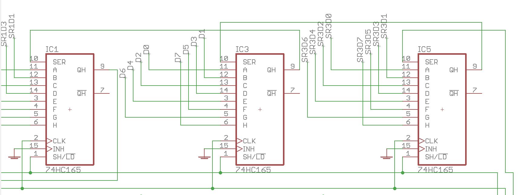
IC2 is the sink side of the matrix; you can see the sink part of the matrix on the left. MIOS pulses each output in turn and this allows the switches to conduct to 0V when pressed (also lighting LEDs when that column of LEDs is on). This registers as a switch press in MIOS by the 165 inputs going low.
IC3 is the DIN part of the matrix. D0-D7 represent the switch columns and there are eight per board from left to right. D0-D7 connect to the anodes of diodes located above Matias switches and beside MEC switches.
As you have a functional lemec board, you can compare voltages on the two. The only difference with the _R board is that there are three extra shift registers (74HC595) at the start of the chain.
Because you have some activity with encoders, the issue lies with either the DIN or sink side of the matrix. Do all encoders work? If so the SC, RC2 and SI lines are all fine. Check that the correct resistor networks are installed (also the orientation), check that you have +5V on all aforementioned 4148 diode anodes,
thanks that definitely gives me a better understanding of how the button matrix is working. I’ll try tacking down the cc pin of the superfluxes tonight.
All of the encoders seem to be working fine, I can see the CC values increment and decrement correctly in MIOS Studio.
As much as troubleshooting can be frustrating it definitely helps teach me about circuit design! Appreciate the hand holding.
Definitely looks like something is up around IC2
Pins 15, 1-7 (QA-QH): 0v (pins 3-5 seem to occasional show .001v)
Pin 9 (QH*):.422v
Pin 10 (SCL): 4.8v
Pin 11 (SCK): 2.7v
Pin 12 (RCK): 4.8v
Pin 8 & 13 (GND): 0v
Pin 14 (SER): .46v
Pin 16: 4.8v
On the working LeMEC_R:
Pins 15, 1-7 (QA-QH): .586v,
Pin 9 (QH*): .493v
Pin 10 (SCL): 4.8v
Pin 11 (SCK): 2.7v
Pin 12 (RCK): 4.8v
Pin 8 & 13 (GND): 0v
Pin 14 (SER): .422v
Pin 16: 4.8v
I reflowed the resistors around IC2 just to make sure the top soldering wasn’t bad and confirmed the resistor networks are in correctly they’re the same part and orientation between both boards. Also checked all the 4148 diodes and the voltage seems good (4.8v everywhere).
Thanks for the voltages, so the issue seems to be on the sink side of the matrix.
As you’re troubleshooting the _L board and the _R board works fine, it would seem as though the data is getting though correctly.
Could you try the following commands in MIOS terminal:
set dout d0 1 %turns first output on set dout d0 0 %turns first output off set dout d7 1 %turns eighth output on
Here you manually set the pins, so this can rule out any errors from the software side. You can also try it with the .NGC loaded. When d0=1, the first four encoder switches should work when pressed. set d0=0, then d1=1 should allow the first four Matias switches.
If the component values/types, cabling and soldering are all sound, then I’m beginning to suspect a dud IC. Could have been overheated or subject to static for example.
12 minutes ago, latigid on said:
Thanks for the voltages, so the issue seems to be on the sink side of the matrix.
As you’re troubleshooting the _L board and the _R board works fine, it would seem as though the data is getting though correctly.
Could you try the following commands in MIOS terminal:
set dout d0 1 %turns first output on set dout d0 0 %turns first output off set dout d7 1 %turns eighth output on
Here you manually set the pins, so this can rule out any errors from the software side. You can also try it with the .NGC loaded. When d0=1, the first four encoder switches should work when pressed. set d0=0, then d1=1 should allow the first four Matias switches.
If the component values/types, cabling and soldering are all sound, then I’m beginning to suspect a dud IC. Could have been overheated or subject to static for example.
Yep I’m beginning to think the same! I ran the following (minor correction to use 0 instead of d0, MIOS didn’t like the d):
[1240259.981] set dout 0 1 %turns first output on
[1240260.142] DOUT Pin 0 (SR#1.D7) set to 1
Tested the encoders again with no luck. Then reset to d0=0:
[1240259.981] set dout 0 1 %turns first output on
[1240260.142] DOUT Pin 0 (SR#1.D7) set to 1
Then enabled d7:
[1240259.981] set dout 0 1 %turns first output on
[1240260.142] DOUT Pin 0 (SR#1.D7) set to 1
Tested the matias switches with no luck.
I tried once immediately after booting up, and once after loading seq_l. Same results both times. I’ll remove the IC and get another one ordered. Thanks again!
Ah yep,
set dout x 0|1
is the correct syntax.
You could try the same on the second 595 chip, these would be dout 8–15.
You’ve copied the same terminal data each time, but I assume you turned the correct outputs on and off. Note that pressing the up arrow on the computer keyboard will go through a history of the terminal commands.
Whoops, forgot I have to right click to copy the terminal data instead of using Ctrl+C! Here’s the actual input:
[1240259.981] set dout 0 1 %turns first output on
[1240260.142] DOUT Pin 0 (SR#1.D7) set to 1
[1240383.356] set dout 0 0 %turns first output off
[1240383.517] DOUT Pin 0 (SR#1.D7) set to 0
[1240401.956] set dout 7 1 %turns eigth output on
[1240402.117] DOUT Pin 7 (SR#1.D0) set to 1
Hah I’m an idiot and just realized % is the MIOS comment character! I was wondering what %turns was referencing.
Testing the LeMEC_R - it seems to be booting up with the dout pins enabled and doesn’t seem to react if I manually set the value to 0. Both buttons and encoders all fully function.
The core has NG loaded but behaves this way with and without the sd card loaded. Is that suspicious?
Edit: For the next person that does this - YES this is suspicious, doing the above test on the second board caused lights to turn on on the JA board. If you have the boards in the correct order this should not happen!