Ugh this will teach me not to work on projects until 2am! I had the LeMEC boards in the wrong order.
Everything is working great now. So sorry for wasting your time Peter and Andy! Though I think some good troubleshooting steps came out of it nonetheless.
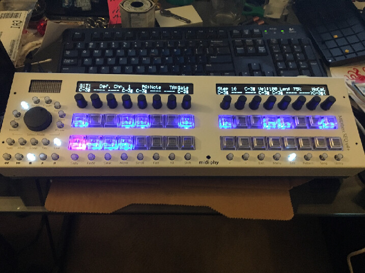
No worries, you provided good info (voltages and pictures) and had a decent attitude. If it works, we’re very happy!
Got all the MEC switches/LEDs installed and working correctly now!
Having a strange issue with the Matias switch LEDs - all the buttons and encoders on both boards are still working.
I initially had a few red LEDs that weren’t working, I’ve replaced those with the spares and they’re great now, red lights are all good on both boards. Blue lights working great on LeMEC_R.
On my LeMEC_L (I’ve got the right board this time ) every 4th blue LED isn’t appearing. Top row missing #4 and #8, bottom row missing #4 and #8. I did replace the #4 bottom row LED to get the red working again but the blue problem still happens.
Had a few more hurdles to get over (bad I2C cable) but it’s alive!
Still have a couple things to finish before calling it complete - beat LED and I ran out of 10 pin connectors for the LineTX cable from LeMEC_R, but it’s looking good!
Thank you Andy, Peter, Bruno and the rest of the midibox community for all your patience, wisdom, and troubleshooting help! Thank you TK and Adrian for your efforts on this project as well! Can’t wait to learn the ins and outs!
i have a problem on the LE-MEC LH after pushing on the left most encoder cap the leftmost row of buttons doesn’t work any longer:
leftmost encoder click, leftmost upper and lower DIN and MEC don’t work any longer.
leftmost encoder turning works and the LEDs are also ok.
i suspect something got shorted as i pushed on the cap. any hints at which components i should look at
(and if i can fix it without desoldering all the Matias switches …)
On lemec_L, left side and both versions, right side, the encoder can touch the header pins. Best is to trim both sides (encoder pins are easier) first and also put a piece of kapton tape or similar between.
From the sounds of it, you followed the testing procedure and had all DINs working before soldering in the Matias?
Please try to isolate/insulate first and see if that fixes the issue. You can also check if there are longer through-hole components (especially diodes) that short out in beween.
If not, please upload a good photo of the rear of the assembly and I will try to help.
You might be able to remove the Matias switches (if really necessary) with your soldering iron heating both pins at once and pulling it out with the other hand/use a vice. A simple vacuum pump can also work wonders.
If the LEDs still work, then the sink side of the matrix is okay. Not sure what could be fried just from pushing together.
ok … so i desoldered all the Matias (ripping off most of the pads on top …), clipped everything on the Enc-Plate even more and also the resistor networks and soldered back in the Matias … it works now
(resoldering the Matias is not recommended - one of the more stupid mistakes i’ve made. it would probably be an idea to provide a kapton isolation sheet in the shop to prevent this?)
i loaded seq v4+ and started testing a bit. this went fine until i tried to go back to midibox ng where the flashing failed halfway and i got stuck in bootloader mode.
now when i powercycle the core is not detected any longer in a MIDI scan and does not show up in the USB device tree (i’m on macOS)…
the green led on the back of the Core still flashes slowly when i power the Core but i don’t get the bootloader message on the screen.
maybe i’m stuck in some kind of low level boot mode? any suggestions?
At least on Windows you should power cycle the Core between updates. (EDIT: I mean close and restart MIOS, the MCU is automatically reset after updating.)
If you really can’t get it to boot/be detected any more, JPA0 is there to help on the wCore PCB. If you stuff this jumper, the bootloader will hold during startup. Normally you can then flash in another .hex again.
also had to delete the previous MIOS32 entry in macOS Audio Midi Setup to bring it back correctly … MIDI isn’t really as smooth under Mac as Peter suggests…
time to sleep, those were enough careless mistakes for today… tomorrow i have to debug a real CAN buss system at work …
I’m building a V4+, and just had my first screw-up… I managed to solder in the wrong directions the gold pinheaders of the wCORE. And of course realized that after having soldered 8 of them.
I tried to desolder them, using desoldering braid and pump but had no luck so far… so I was wondering what would be the best option between clipping off all the pinheaders and just reinstall new ones (I guess removing the solder without the headers in the way would be easier ), or keep trying to desolder and therefore take the risk to overheat the board?
I would recommend to desolder the pins one by one and cleaning the soldering joints afterwards with the desoldering pump. just heat them up and use tweezers to pull them off.
I would recommend to desolder the pins one by one and cleaning the soldering joints afterwards with the desoldering pump. just heat them up and use tweezers to pull them off.
+1, remove the plastic part if possible and just go one pin at a time. Normally you can get a flat tool or blade underneath and the plastic part should lift out.
By gold pinheaders, do you mean shrouded headers? If you don’t have replacement parts available, normal unshrouded pinheaders also work (I normally use those and check the orientation carefully before connecting IDC cables.
Thanks for your advices! It took quite some time but I managed to desolder all the pinheaders, by lifting the plastic parts and desolder the pins one at a time, as suggested. Even with desoldering one pin at a time, it was a lot more tedious that I thought, now I just hope I didn’t damage the board too much and that the rest of the build is gonna go fine
I meant normal unshrouded pinheaders (Hawkeye refers to them as ‘gold pinheaders’ in the V4+ build tutorial).