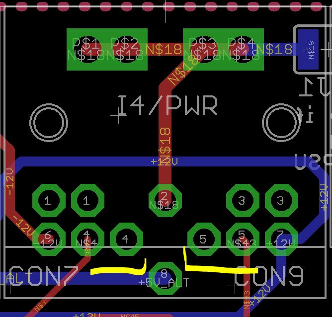
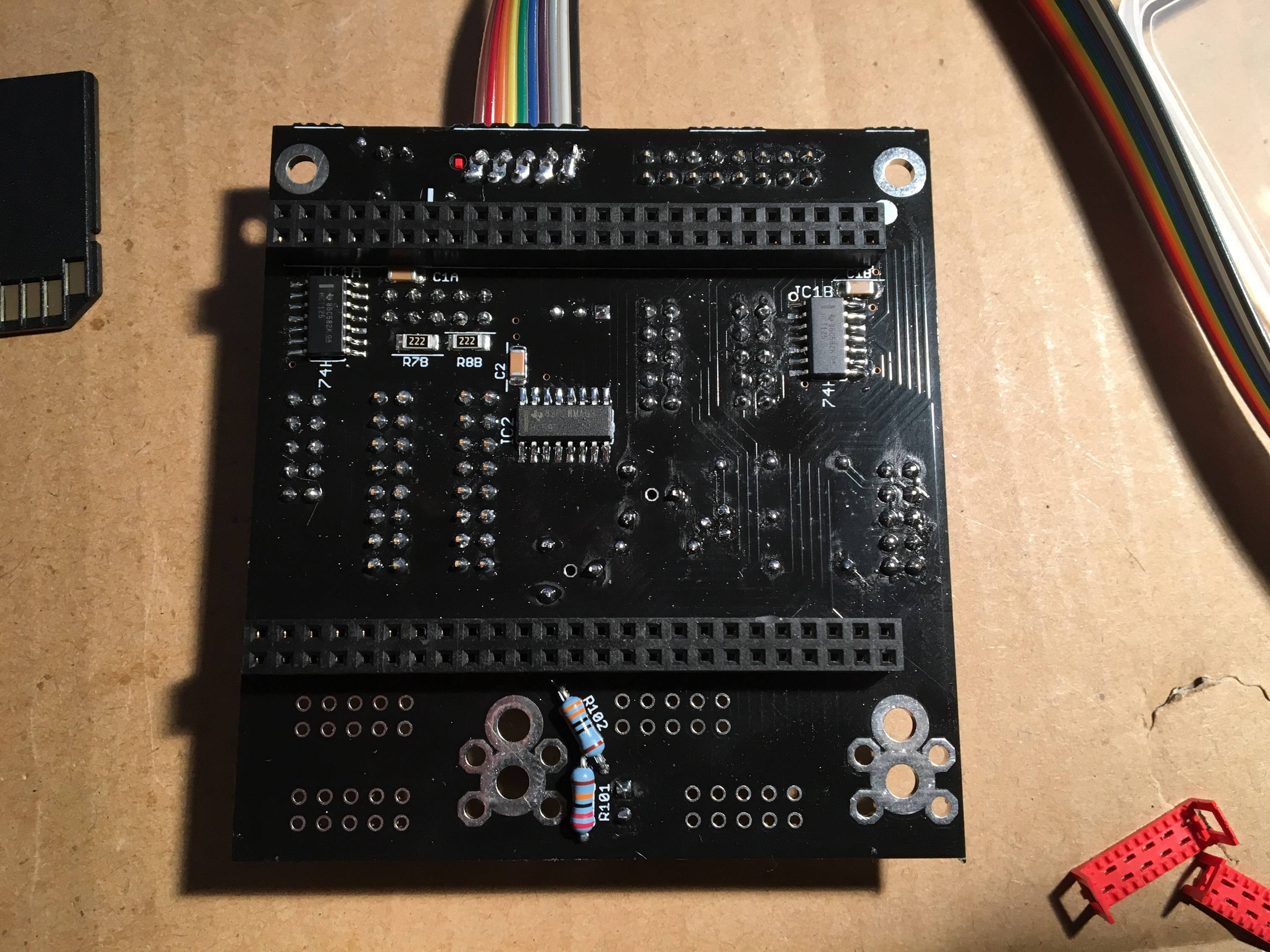
If you wish, it is possible to bridge the pairs of pins 4/4 and 5/5 as shown (viewed from the top of the board). It isn’t done by default, as simultaneous use with a BLM would cause a conflict and perhaps an expectation of an “extra” MIDI port. If you and any future owner of the SEQ are aware of this it should be okay.
For future case production, you can maybe open the metallic plates between the two left mounting hole and use this type of header:
Just an idea, cheers!
Bruno
A good idea and one I had considered, but I think the cutout would weaken the plate too much there. Plus, the clearance to the I2C board will be quite close when the case is in rack mode.
I had a look at headers mounted to a tiny PCB, but I think there’s just not enough room, even with micromatch or “paddleboard” type. Consider 10mm spacing, 2.54mm plastic standoff on a straight-pin header, then a 1.6mm carrier PCB. I didn’t find a header lower than that height difference. I would suggest to put a sliver of kapton tape on the components/IDC.
Of course, you already though about it
I understand about clearance and availability, that’s something I didn’t check and I totally believe you. But if you have to do it somewhere else don’t be afraid to weak the plate, in this example the plate is very well supported on the side and the ‘weaken’ part only supports the LCD, if you need to do it in the future check with Adrian but I think it’s very solid metal, not bending alu, and this is not a problem.
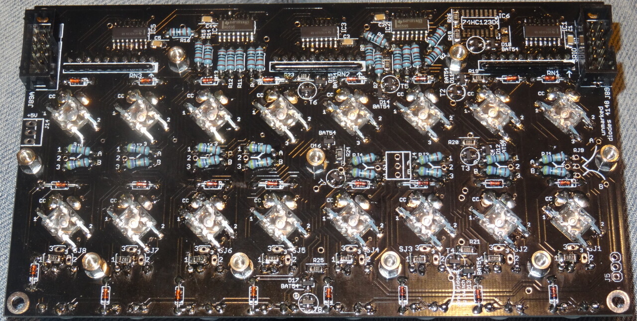
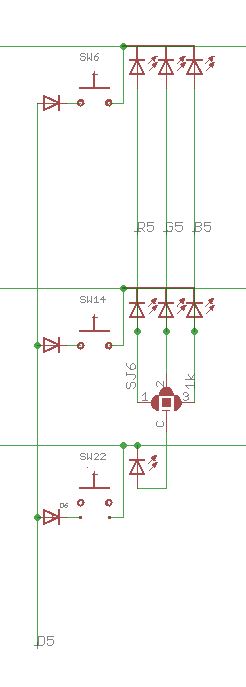
I have a problem with the superflux LEDs, more precisely with the 6th LED of the second row (on the smaller board). I am on the red/blue color scheme. The fluxtest does not light up the red LED on the mentioned superflux LED, but everything else works. The LED itself is working, though - when I separate it from the circuit and test it with the multimeter, all three colors work, also red.
Where is this specific LED connected to? Should I search for a short circuit somewhere?
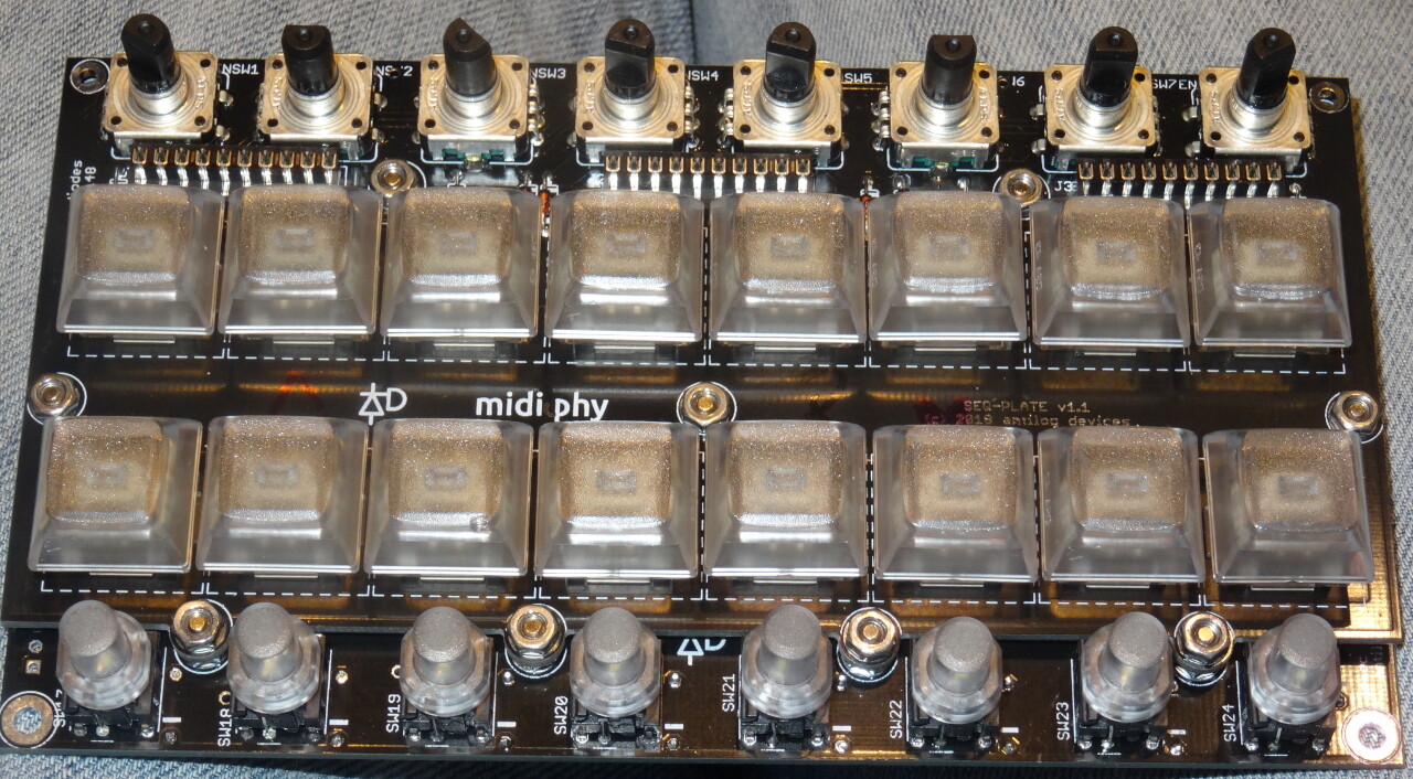
Here you have a photo (or two). In the upper one, the culprit is in the second Mathias row, the sixth from the right (third from left)
2 hours ago, latigid on said:
Is the cathode pin correctly soldered?
Yes, as the blue LED will work flawlessly.
2 hours ago, latigid on said:
Do the DINs work?
Yes, all buttons and encoders work as they should, on all boards.
2 hours ago, latigid on said:
When you say you’ve isolated the LED, you removed it?
Yes, that’s right. Outside of the circuit, all three colors will light up when testing. Inside the circuit, I cannot get the red LED to light up with the multimeter.
2 hours ago, latigid on said:
Did you try one of the spare parts?
Not yet, because that possibility does not seem logical to me, as the LED works as it should when removed from the PCB.
2 hours ago, latigid on said:
You could try to temporarily short to the other red LED in the column or the adjacent cathode in a row.
Ok let’s say I do this and it works, what does that tell me?
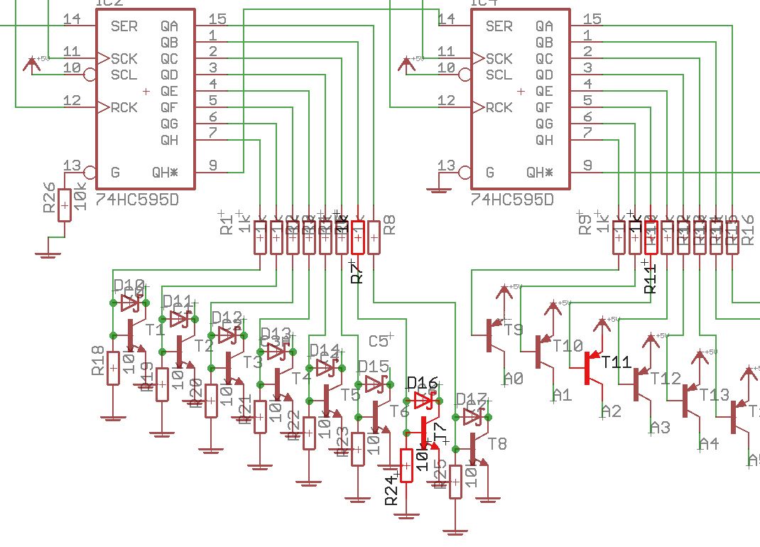
In order to being able to do my own thinking as well, the schematics would be really helpful. Are these available somewhere?
Thanks for the photos. From the looks of it, you didn’t use that much solder on the LEDs. Did you try reflowing them?
What is the forward voltage of the LED? If it is too high, it could indicate that the soldering temperature was too hot. As everything else works, I don’t see how it could be anything else (maybe a broken trace or pad shorted to 0V). Just swap the LED in this case.
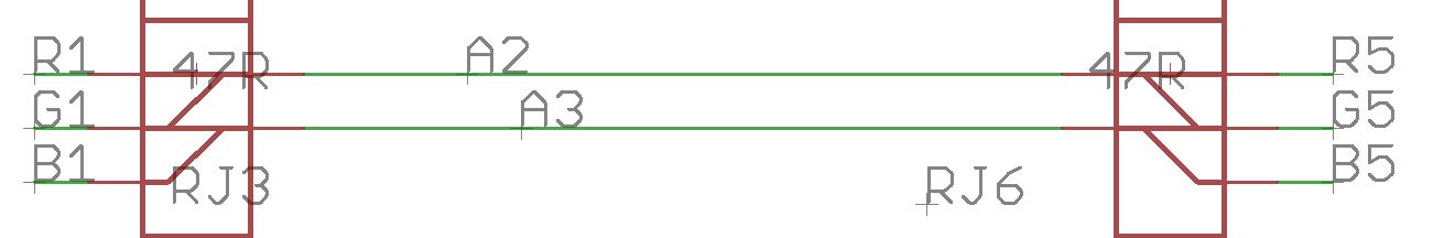
Hence: manually connect the column of the upper red LED to the lower one. If the LED lights, then there is a missing connection between RJ6_1 and the LED. Also test for continuity between the red anode pad and 0V (ground).
Connecting the upper red LED to this one did not help - it was still not lighting up in the fluxtest.
Replacing the LED helped, BUT: after unsoldering it, outside of the circuit, all three colors of the presumably faulty LED light up, and with the expected brightness.
I’m dead sure this was not a soldering issue. Question: what was it then?
There is a number of possible reasons, from electrostatic discharge, shock (dropping) it, to that one not being as resistant to heat, a slight manufacturing diversion, or soldering it for one second to long - maybe the soldering iron was over the central part while soldering…
We had some issues with the red ones in the current batch, that’s why we test-burn all of them for a few hours in LeMEC conditions (assuming you are using 47R) and only ship good ones, Andy has built a cool testbed PCB for it - which could also be used for MIDIbox RGB pixel graphics arrays later on, we will add it to the shop, when we have a bit of time.
So, to answer, either this one was bad undetected, developed the fault after shipping, or the handling caused it, it is impossible to say now - that’s why we put 5 of them for free into every bag of 35, so you have replacements.
Can you measure the red forward voltage and compare with the other ones you have in reserve? If my theory holds, its Vf should be significantly higher than on the others, that’s why it still lights up when using your DMM in diode test mode and does not light up in the LeMEC.
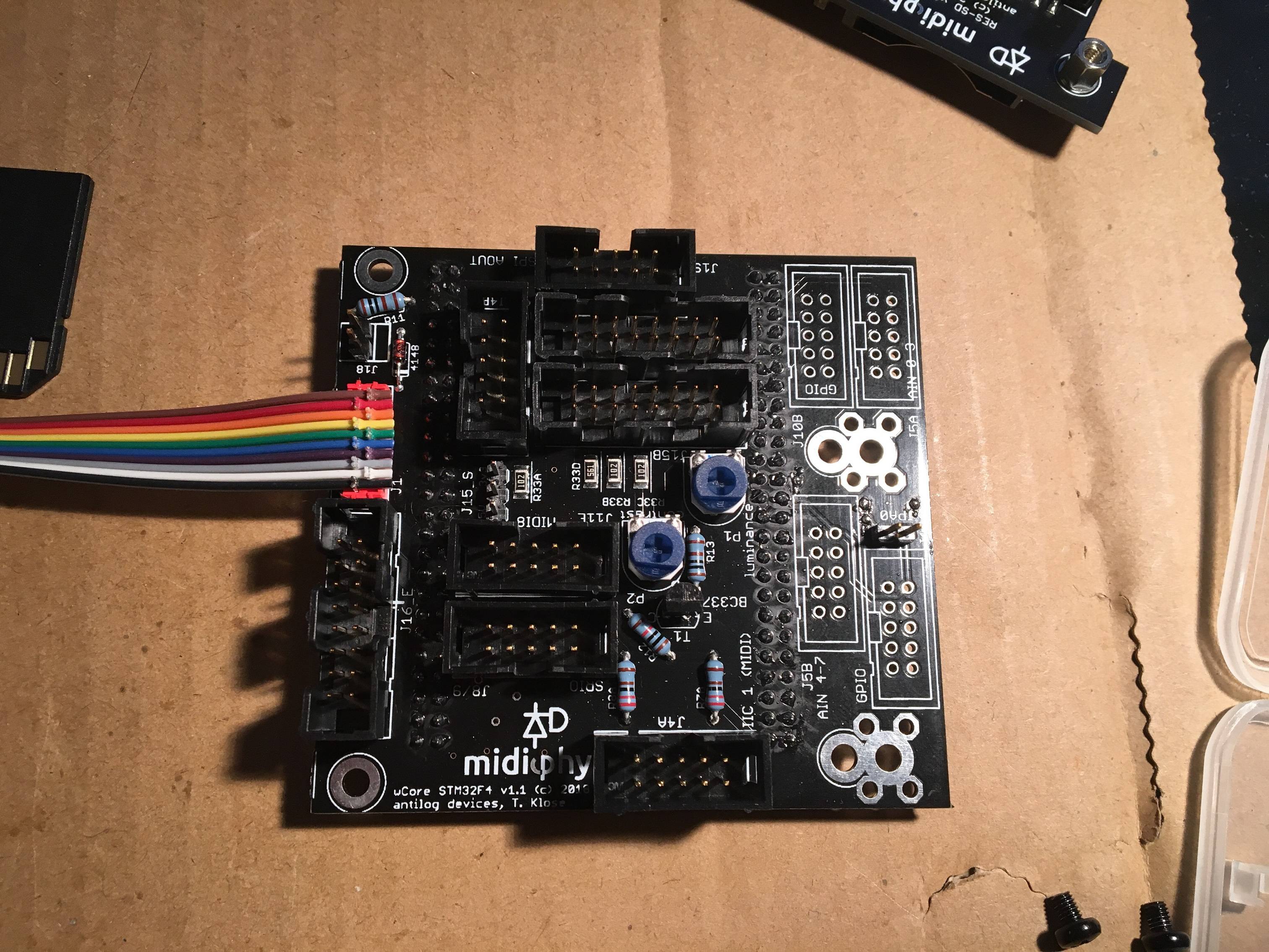
don’t know if this is the right place. i have finally finished the AOUT NG and DOUT board to add some cv/gate/trigger to my seq v4+.
I’m a little confused about the interconnections and jumper settings of the pcbs. inside of the sequencer i have the LINETX connected to the core like shown in the video but since the pcbs are a new revision and the J-headers are named differently then on the LINERX/TX-page i’am afraid of damaging something..
basicly i would like to do the following:
- could anyone please help me on how to do the connections and setup the jumpers?
-is it necessary to use an additional power supply when using 0-5v only?
-what is the pinout of the AOUT port of the LINERX?
many thanks
rbv2

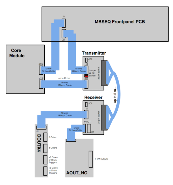
As no serial inputs (switches) are used, the J2_SI setting is not important. If you use an AOUT_NG, then JAOUT offers 1:1 pinning, but it overlaps with the LINE_RX J19. The pinout is as shown in the ucapps schem.
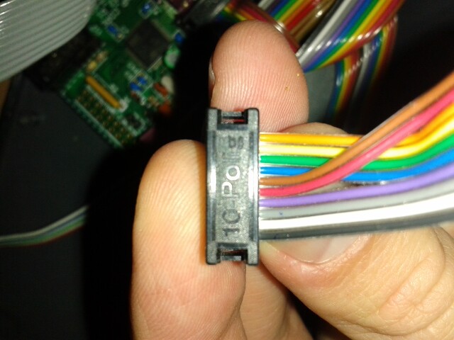
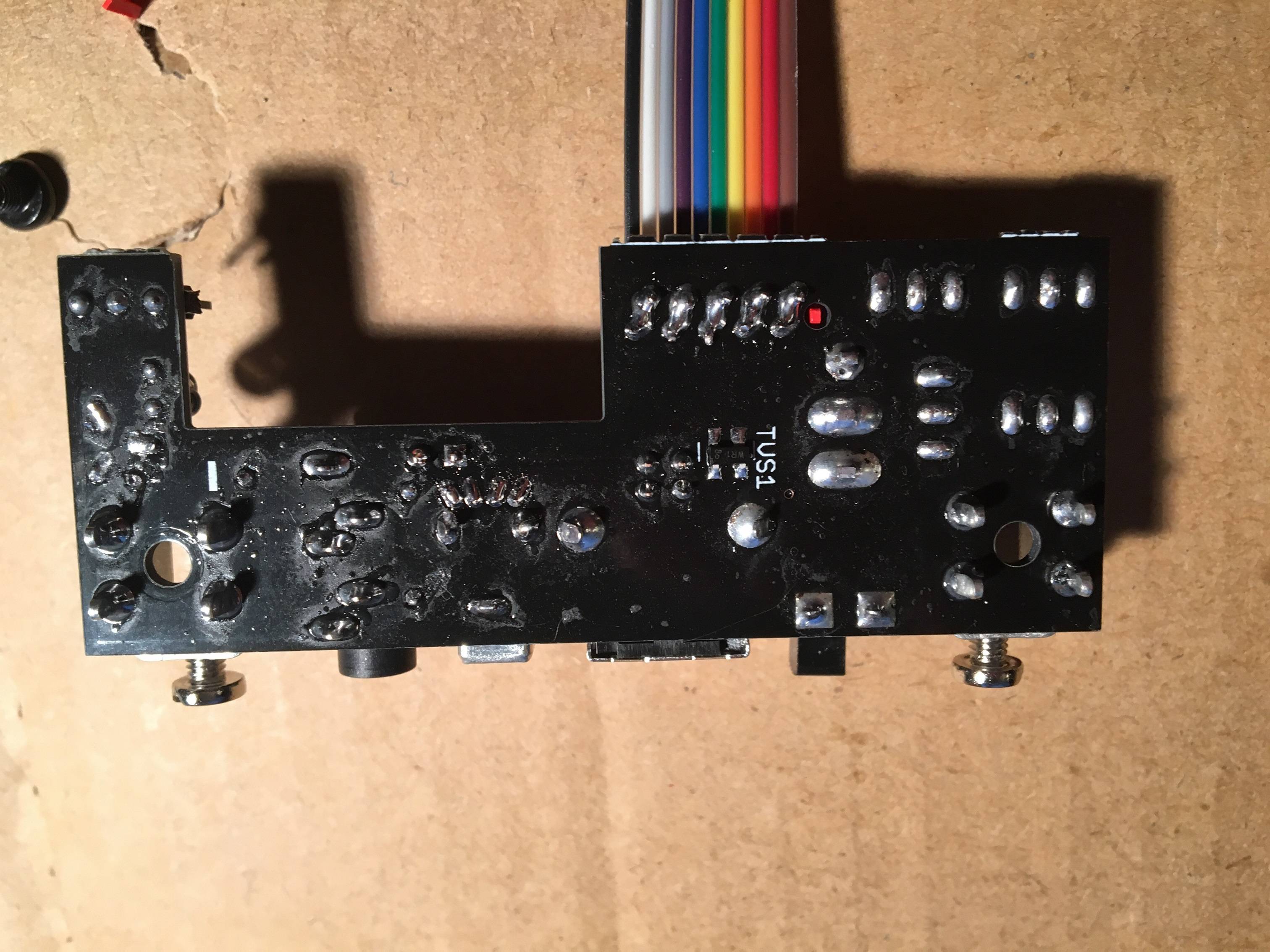
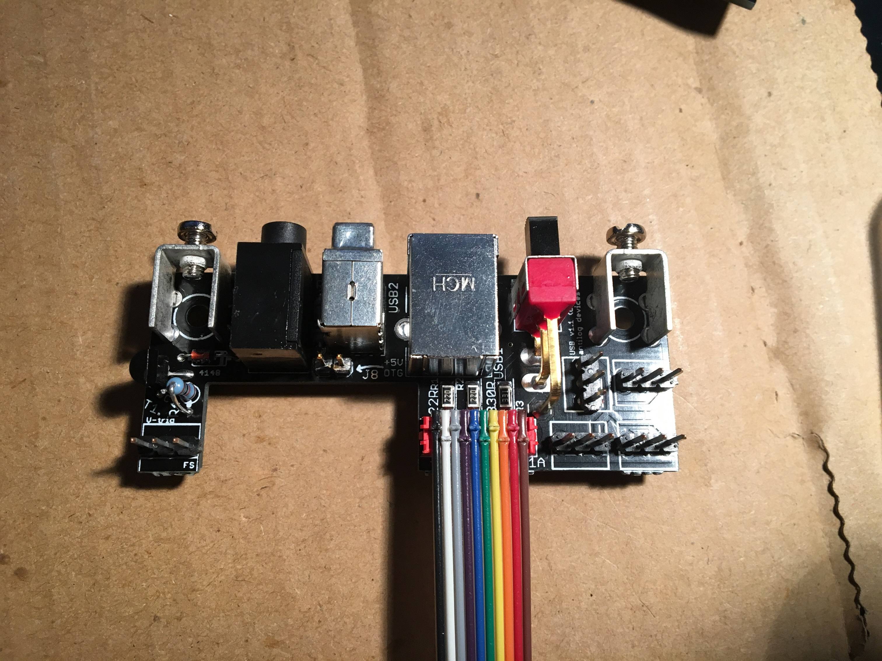
If you’ve already soldered J19, you can rearrange the ribbon cable as shown:
Thereafter use the top row (opposite side to the notch in the header) to connect to AOUT_NG J1. The other side is connected 1:1. These days I would put the black cable on the other way, but it doesn’t really matter.
For midiphy LINE_RX, I recommend to use a dedicated +5V supply and leave J3 unjumpered. The ICs use quite a lot of current (100 ohm terminators), which isn’t transmitted well down a DB-25 cable.
At first, maybe try to keep J3 jumpered and see how the performance is.
You can think of the J8/9 SRIO chain (or J19 SPI) like a power buss, so if there is a power supply connected to the cable, the chips on the line driver will receive power that way. But if you think of where that power comes from it goes all the way back to the Core USB connector. Thus there is the option to unjumper J3 and supply the MIDIbox buss internally (like in a Eurorack case). This was not thought through extensively before, which is why I’ve designed something much more suitable for racking in a case, with lots of different power options (still needs testing but should be available soon).
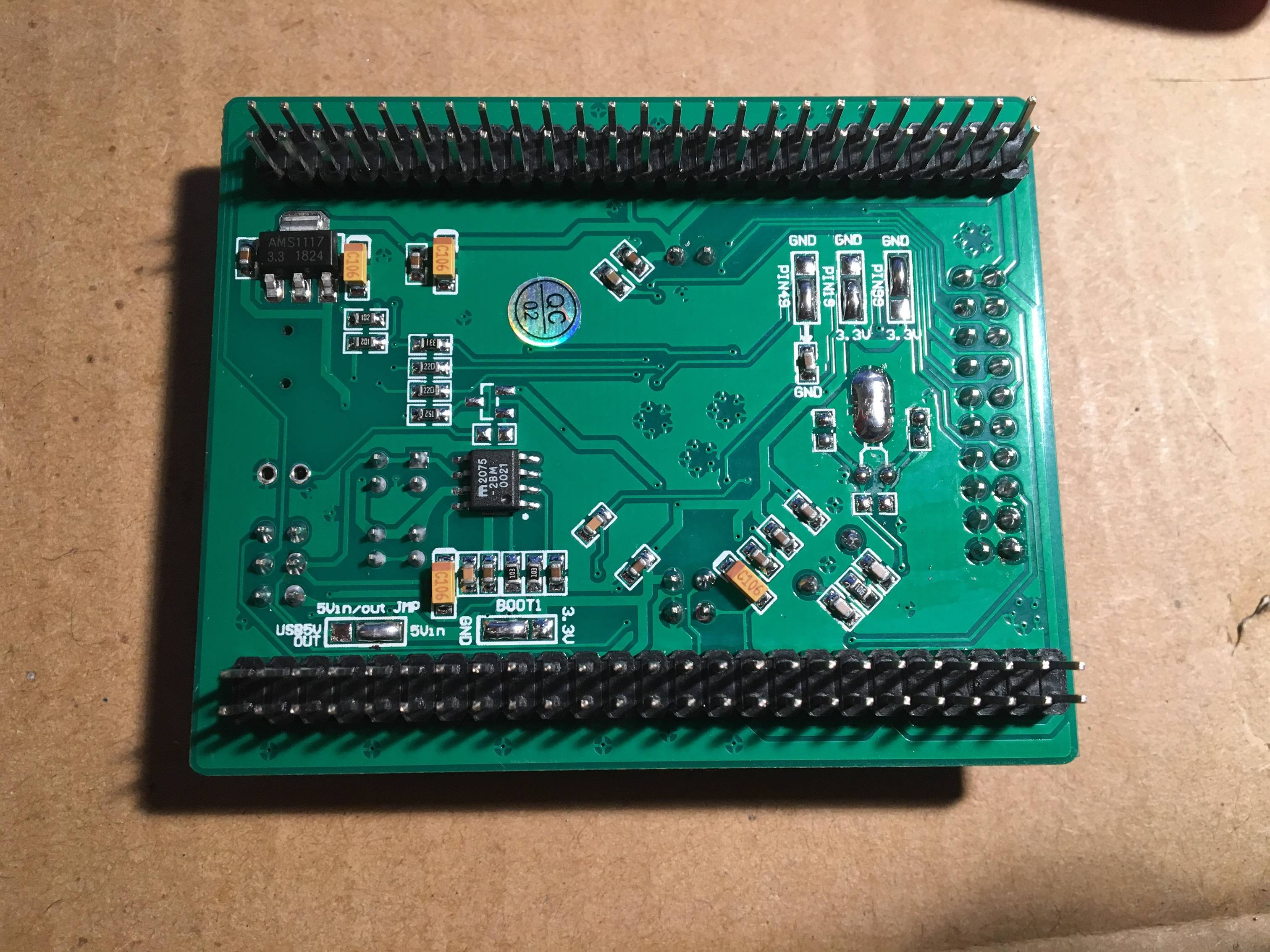
One option for a separate +5V is to put the J19 connector somewhere in the middle of your ribbon. The first four wires are 0V|0V|+5V|+5V, so if you have a PSU handy you could connect those there. J3 should be unjumpered in this case. AOUT_NG would share the same +5V. This buss-power regime is not optimal, but it seems to work okay. Better would be to “star wire” each PCB back to the source PSU; that way the return currents should interact less.
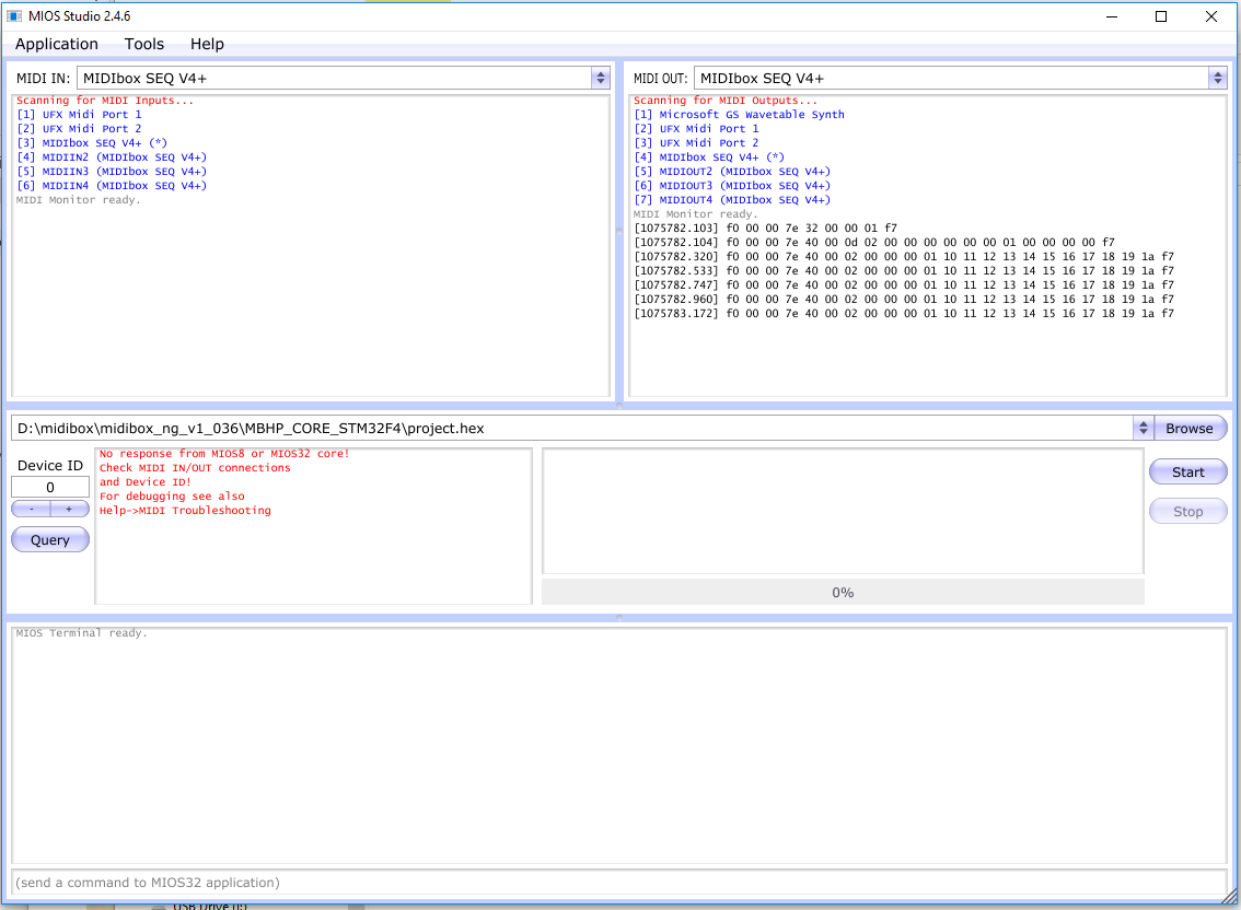
Hmm scratching my head a bit here - over the weekend I reconnected the USB pcb and core pcb and was able to upload the seq v4 project.hex file successfully.
I just finished the JA pcb and went to upload the ng_v1_036 project.hex file for testing, but MIOS studio doesn’t seem to recognize my core at all. MIOS Studio does see MIDI IN/MIDI OUT named MIDIBox SEQ V4+ (and the other 3 seq channels), but no response from the core.
Troubleshooting steps so far:
Removed SD card PCB from core.
Inspected the pcbs for shorts but don’t see any. I reflowed a few joints just to be sure.Inspected 10 pin cable connecting the USB pcb and core pcb but it looked good.
Tried changing the device ID in MIOS Studio
Tried unplugging RME audio interface to remove other MIDI devices
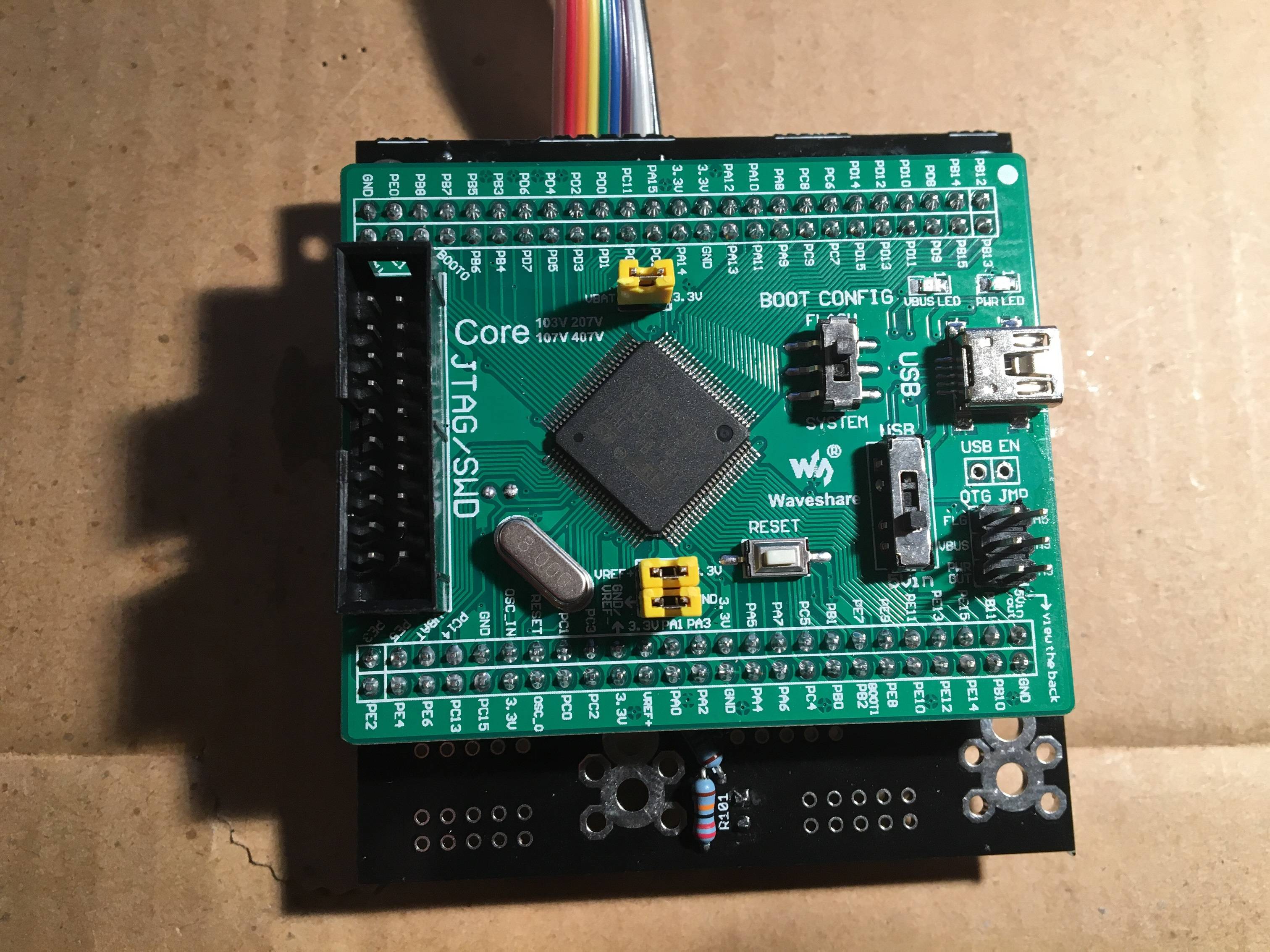
STM has the three bottom jumpers removed, power from 5v, and BOOT CONFIG set to FLASH, the other three jumpers are still in place.
I looked through the MIDI troubleshooting guide but it seemed to be more focused on PIC troubleshooting, if I missed something apologies!
Have you tried restarting MIOS Studio between updates?
Jumper settings appear correct.
You can also measure resistance between the USB B port (with power off) and PA11/PA12 on the socketed Waveshare MCU breakout, should be 22R.
Wow - kicking myself here. Simply restarting MIOS Studio brought it back to life! I was able to get the core showing again and uploaded the MIDIBox NG app as well, though I did need to restart MIOS Studio again for it to show (running on Windows 10).
Appreciate the super fast responses!
Thanks for helping with the pictures ilmenator, not sure why I kept receiving -200 errors during file upload.
Congrats on getting it working again! As you heard my grumbling passage in the video tutorial “i should really get a mac” - really meant that at that time, as Windows seems to have quite buggy MIDI-USB. Restarting MIOS Studio or even Windows can help quite often.