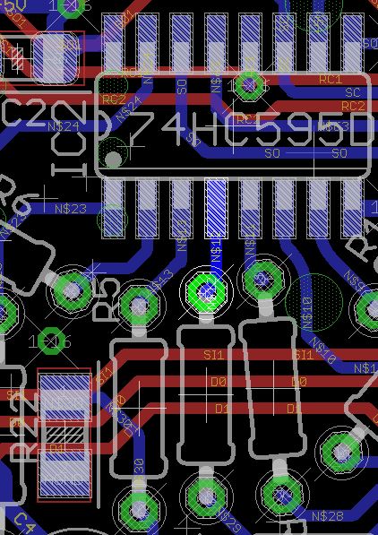
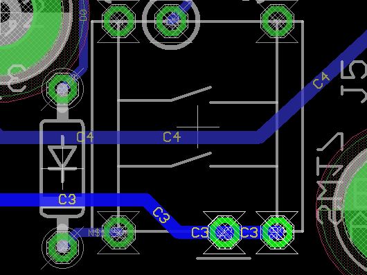
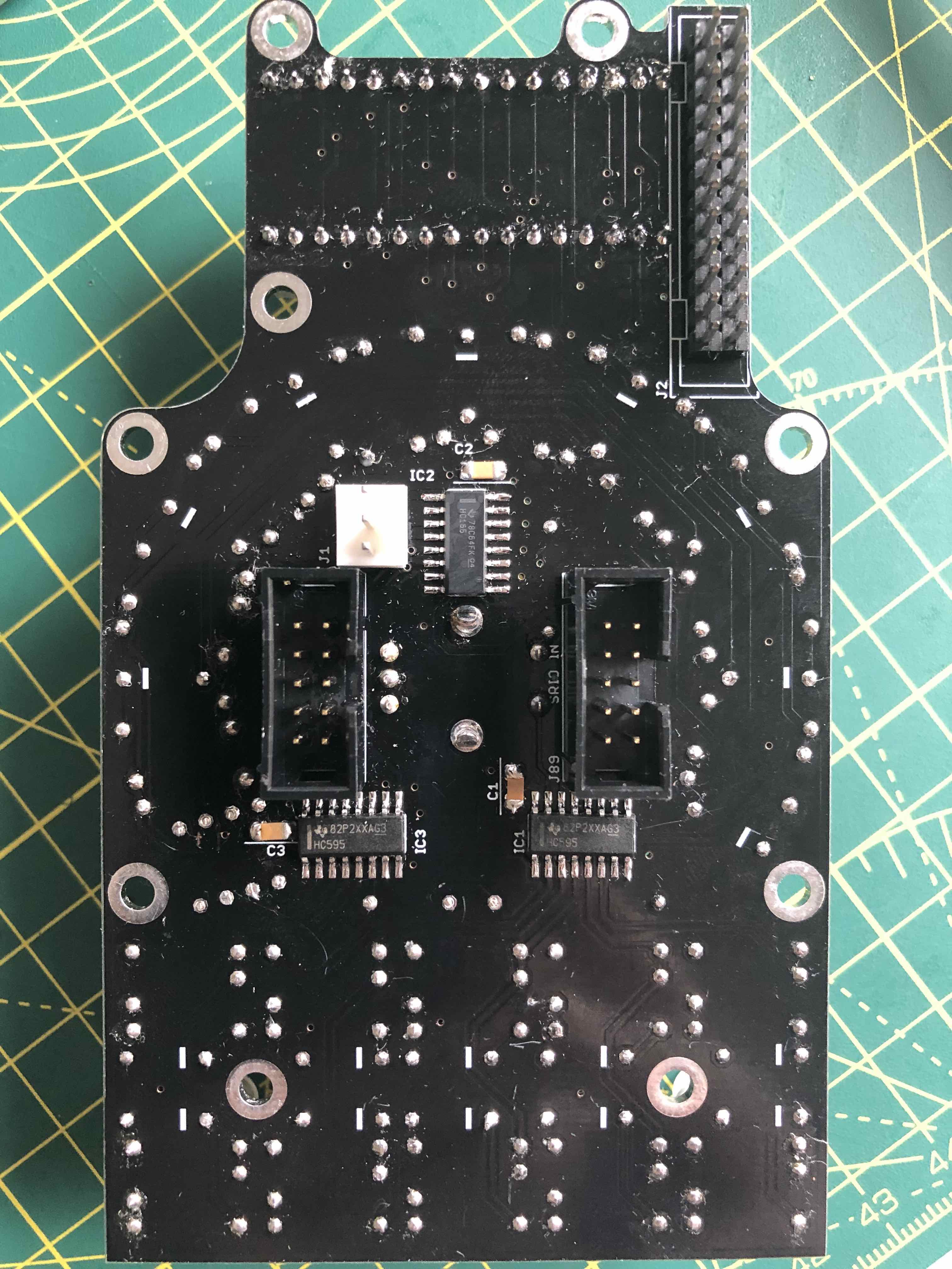
Let’s trace the cathode signal back to IC2. We’re looking at the rear of the board.
The cathode signal is as shown. It should be common to the same positions on all switches 17-20.
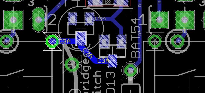
After jumping over the bridge (curved silkscreen line) it connects to T4/D13. The issue is likely around this area. The signal continues to R21. Check for continuity between the pads and 0V (ground). The left sides of T4/R21 are intentionally grounded.
You should be able to measure continuity between the pins of all points of this circuit, with no shorts to 0V unless stated.
Test the anode sides (non striped) of diodes situated next to the MEC switches. They should be common with the diode anodes of the same row column, especially seeing that the other switches work.
If that helps, please post what the issue was so others can benefit in the future.
More a solved issue for the record than a request - hope this is in the right place?
Day #1 of build and I got through to finishing the SD card board build. Thanks to Peter’s video! It’s a great help.
When I got to attaching the core + USB + Wavemaker elements to MIOS Studio, I couldn’t get MIOS to recognise the new MIDI devices. I’m on a Mac (10.12) Having used the rescan MIDI ports command a few times having checked connections, I went to the Mac MIDI Studio and there it was… nicely recognised. When I restarted MIOS Studio it found the setup and I moved on…
So, I guess the lesson (for Mac users, at least) is that the MIOS Studio warning and the Rescan functionality not working very well actually *IS* true!
Thanks! it was r3. There was a decent amount of solder there, but it had not flowed properly down the hole. Which made it look OK from the top, even with magnification. On to the next phase.
Hi I’m at the point of testing the lemec boards, and if you recall I have some issues with the JA board. As you suggested earlier if the power is ok, at least some of the board should work. I just want to make sure power is ok passing through the board, could you let me know what the voltages should be on the pins for SRIO out? Or point me to a link with it, I can’t seem to find it via search. Thank you!
Nevermind I forgot I can use seq_r to just chain it the other way around. I’ll figure out the JA board later. Thanks though
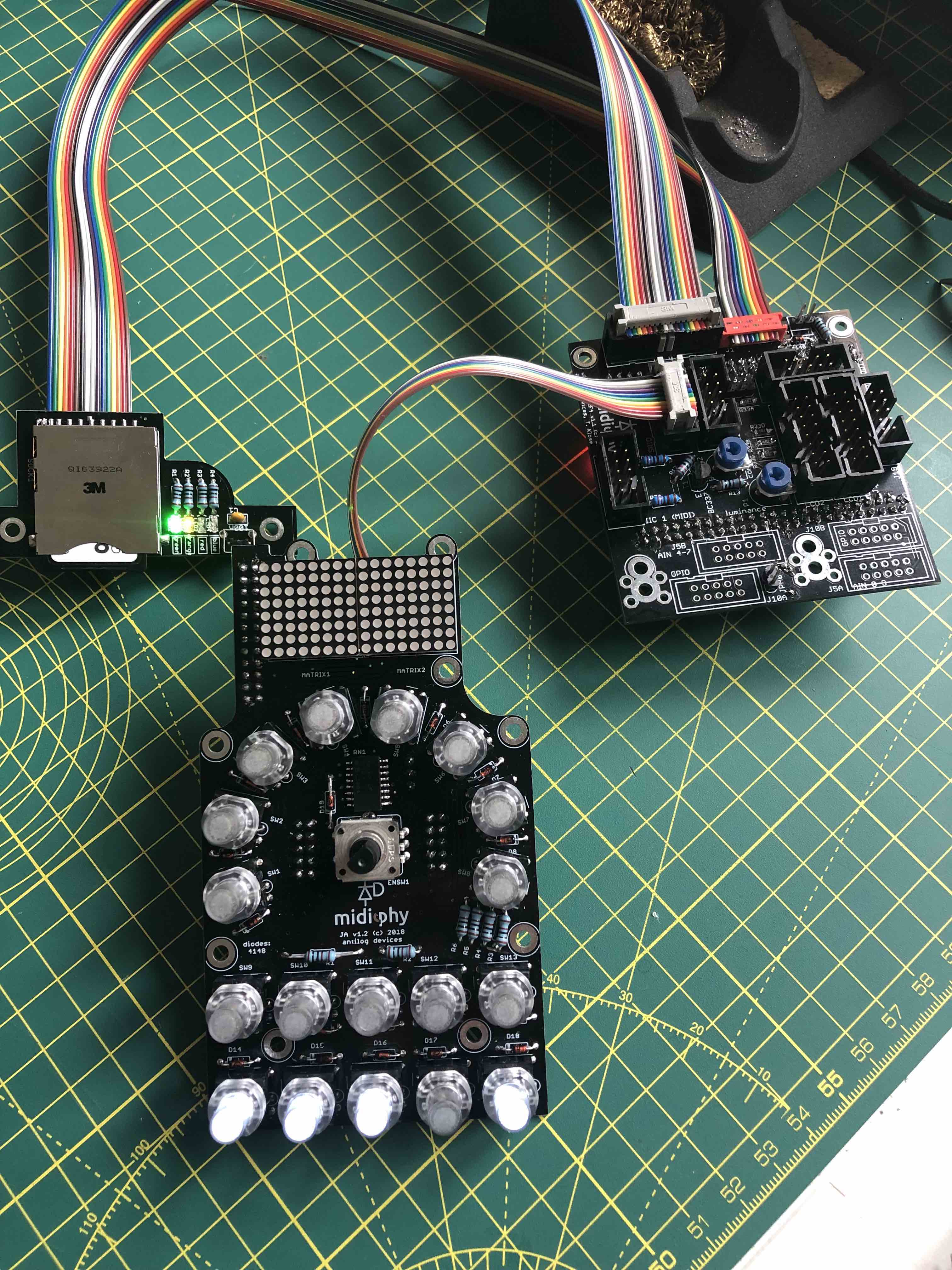
Just completed JA board and moving on to testing. On boot/reboot, I’m getting buttons 1, 2, 3 and 5 of the lower row lit on JA, and green light on SD board and red power on Wavemaker (see pic).
If I insert the SD card (FAT32 formatted with ther seq_l file in root only), I get solid amber light and flashing blue on SD board and all lights go out on JA board. This sometimes happens afer reboot without inserting SD card, but always if I do.
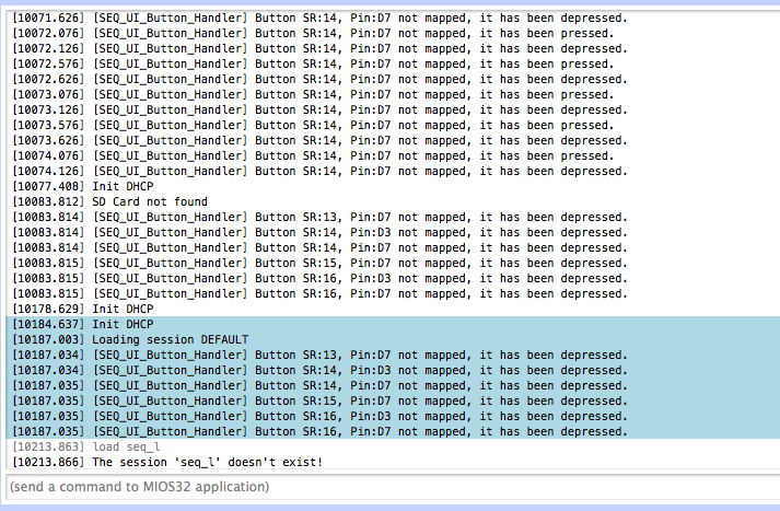
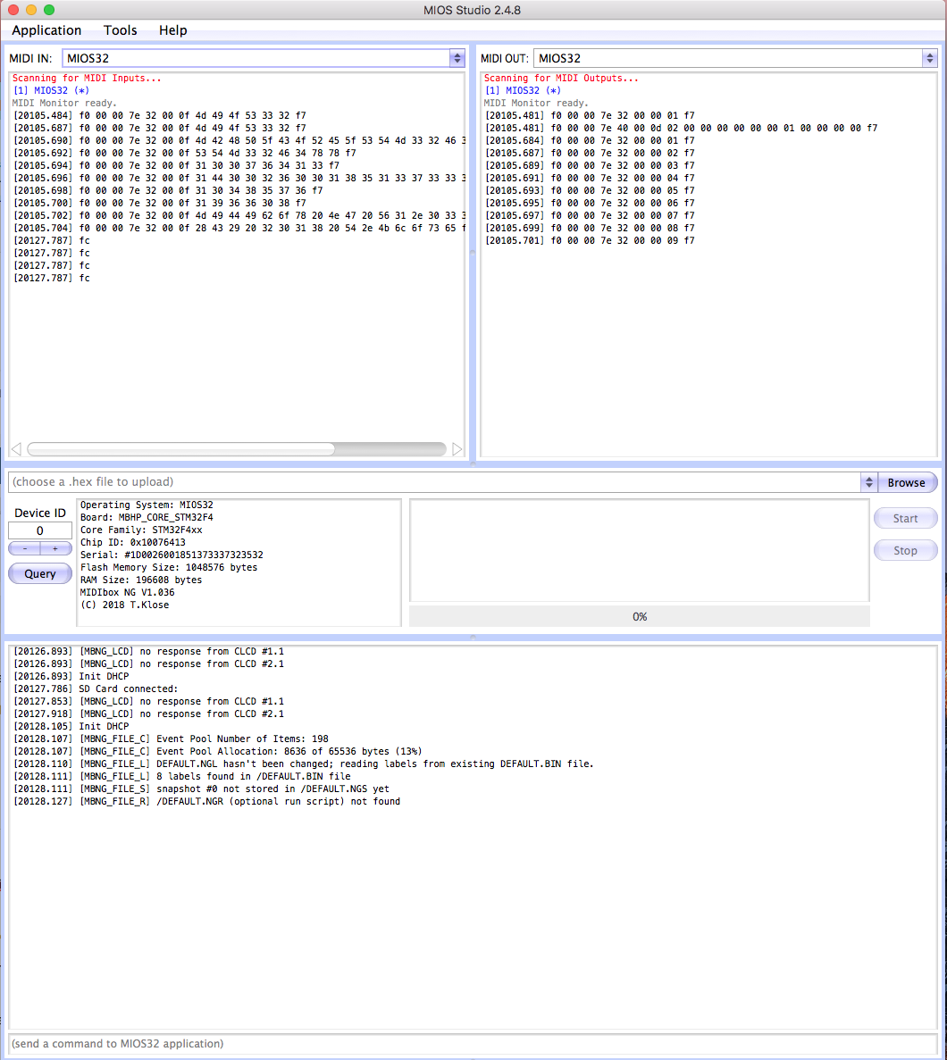
Logging from MIOS Studio looks like:
[blue block was reboot with card inserted, block above was without card inserted]
Feels like card *and* button (short?) issues? I can’t find the button mapping refs through search…
I’ve reflowed the SD card connection - the last two are very tight but I don’t see a short. Can’t see a short on JA board either, but I’m squinting a bit after a day soldering
The easiest place to test for power is on the J14 three-pin connector on the east side of the board. 0V in the middle, +5V above (marked with the silkscreen). Always test that these pins aren’t shorted together before applying power. The other pins I’ve already mentioned I think. The voltages will depend on the speed of your multimeter and would be best viewed with a scope.
For 595 chips: pins 16 and 10 = +5V; pin 13 = 0V (resistance may be 10k).
For 165 chips: pins 3-6, 10-14, 16 = +5V; pin 15 = 0V.
For J89 header, pins 1,2 = 0V, pins 3,4 = +5V,
5 hours ago, niles said:
Hi I’m at the point of testing the lemec boards, and if you recall I have some issues with the JA board. As you suggested earlier if the power is ok, at least some of the board should work. I just want to make sure power is ok passing through the board, could you let me know what the voltages should be on the pins for SRIO out? Or point me to a link with it, I can’t seem to find it via search. Thank you!
First thing to check is if you have soldered the correct resistor network on the JA board?
Second, I think you don’t have MB_NG flashed onto the Core? Maybe the SEQ app is flashed?
4 hours ago, SimonSays said:
Problem #1 (hopefully, “of 1”!)
Just completed JA board and moving on to testing. On boot/reboot, I’m getting buttons 1, 2, 3 and 5 of the lower row lit on JA, and green light on SD board and red power on Wavemaker (see pic).
If I insert the SD card (FAT32 formatted with ther seq_l file in root only), I get solid amber light and flashing blue on SD board and all lights go out on JA board. This sometimes happens afer reboot without inserting SD card, but always if I do.
Logging from MIOS Studio looks like:
[blue block was reboot with card inserted, block above was without card inserted]
Feels like card *and* button (short?) issues? I can’t find the button mapping refs through search…
I’ve reflowed the SD card connection - the last two are very tight but I don’t see a short. Can’t see a short on JA board either, but I’m squinting a bit after a day soldering
First thing to check is if you have soldered the correct resistor network on the JA board?
Second, I think you don’t have MB_NG flashed onto the Core? Maybe the SEQ app is flashed?
Thank you …
You were right: insufficient attention paid to filenames on my part… I still had midibox_seq flashed, rather than midibox_ng. Going back to the tutorial and flashing NG has solved part of the issue.
I’ve got the 2-103 resistor network soldered (ie. not one of the the 1-103s) - I think that is the correct (bussed) one?
I’m still not quite there, though - when I restart MIOS studio my midi ports are *not* named Midibox NG (as per Peter’s video_ but still called MIOS 32. Not a problem in itself but possibly a symptom.
The various .NGC files are being created on the SD card on boot, but I’m still getting some errors in the logs (attached) - some of which look like missing LCD components which is expected.
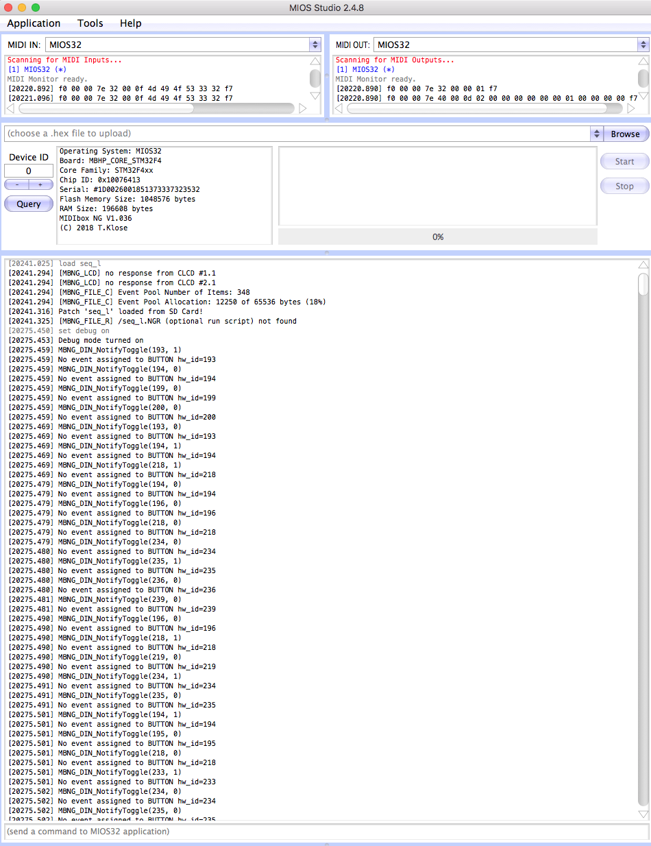
But I’m not getting any response from JA board buttons and, with Debug set to ON in MIOS Studio, I’m getting continuous logs on missing events, etc.
I think as long as you have 4x virtual USB MIDI ports, the naming is not so crucial. It could be worth flashing the bootloader again. But it seems that _NG is successfully loaded and that SD reads work. Sometimes an SD format can also help.
Possible causes of random DIN events:
IDC cables incorrectly assembled (wires shorted together or missing, connectors around the wrong way)
resistor network isolated type; bussed type is correct (ruled out)
resistor network incorrectly oriented
shorts between IC pins
check pins 6/7 as there seems to be some flux/fluff/solder splash etc., also elsewhere on the board.
Floating IC pins: check 165 inputs (pins 3-6, 10-1) are at +5V.
I’m just putting the IDC shrouded headers on the Le Mec boards and I think I’m one 10 pin header short… I’ve checked and the BOM I copied had 17 of them, and there are 18 required on the boards (I’m not including the lower ones on the core or J89* on the larger Le Mec).
Hmmmm…
Is there another part I can salvage from to get the Sequencer working this weekend? Can I exclude one of the line driver boards to begin with, perhaps?
SEQ les mecs, JA = 6
SEQ Core J4A, J19, J11E J19 = 4. J4B is also not required for a SEQ.
Line drivers = 4 (can skip the Receiver if you’d like to build a Euroceiver later)
I2C = 1
MIDI8 = 2 (could skip J2)
Where are your 18 from? Core kit BOM says 11, UI kit says 6.
SEQ les mecs, JA = 6
SEQ Core J4A, J19, J11E J19 = 4. J4B is also not required for a SEQ.
Line drivers = 4 (can skip the Receiver if you’d like to build a Euroceiver later)
I2C = 1
MIDI8 = 2 (could skip J2)
Where are your 18 from? Core kit BOM says 11, UI kit says 6.
I’ve got J4B on Core board soldered… in my defence, so does Peter in the video (and if Peter said “jump off a bridge” in the video, I’d be jumping, obviously )
No drama - I used some un-shrouded double-row pin headers on the R/H Le Mec, for the inter-Le Mec connection,. I also used a bespoke (read: created from 10 pins of socket-to-socket breadboard connectors) cable here as I will also be short 2x 10 pin 3M connectors due to my bad cable above. I can replace these once I’ve sourced new 10 pin IDC parts.
The good news is it all works (cables and connectors, anyway) as the Le Mec testing stage is almost 100% good!
The only issue I can see on that test is thaat the 4th encoder along on the L/H board causes a proper little light show on the JA MEC switches when turned/pressed + turned - also one of the encoders on the R/H board did same but only very briefly and I can’t reliably replicate. I’m expecting this to be some soldering reflow required on 165 and/or 595 ICs on both boards? (Although the light show might be a standard feature?! I haven’t read the manual of watched further into the video yet)
Everything triggers MIOS logging - including the Matthias Switches…
I can’t remember if any of the encoders are mapped to anything. SEQ app or still with _NG?
You can also check if any of the components on the SEQ-plate/lemec short out unintentionally. Normally the issue is with the encoders above the J89/J89A headers. The through-board connectors might also be worth a look.