Exciting! Best of luck with the rest of the assembly.
On 4/26/2019 at 5:42 PM, latigid on said:
Hello,
For testing les mecs, you’ll want the seq_r.ngc.
The easiest place to test for power is on the J14 three-pin connector on the east side of the board. 0V in the middle, +5V above (marked with the silkscreen). Always test that these pins aren’t shorted together before applying power. The other pins I’ve already mentioned I think. The voltages will depend on the speed of your multimeter and would be best viewed with a scope.
For 595 chips: pins 16 and 10 = +5V; pin 13 = 0V (resistance may be 10k).
For 165 chips: pins 3-6, 10-14, 16 = +5V; pin 15 = 0V.For J89 header, pins 1,2 = 0V, pins 3,4 = +5V,
Thanks!
So neeeeeeeearly there…
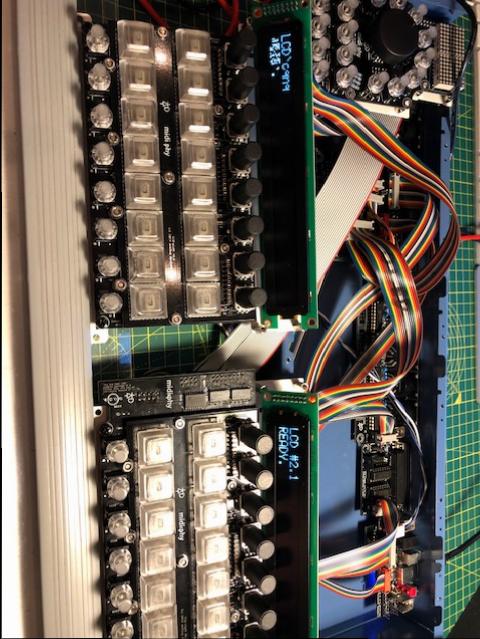
Remembered the 3.3v jumper on the core, put everything in the case (Adrian has done a great job here - built like a tank!), flashed Seq with L/H config and… the right OLED works, the left was gibberish. Rebooted and the left was blank.
I’ll check all the connections, but I found an old thread talking about screen issues with low and/or noisy voltage. Is this still a problem? Could it be the 3.3 vs 5v at the board? Or a need for a cap?
Cheers!
Check R33D (560R not 1k), check the IDC cable strands don’t contact the rear of the OLED PCB. Swap cables to rule out bad cables.
Correct R33D installed, cables and OLEDS both functioning correctly - whatever is plugged into J15A - left-hand screen - shows nothing. The seq is functional - the R/H screen swaps top show whichever half the encoders have been moved for (ie. if I moved encoders 1-8, it shows steps 1-8… if I move encoder 9+, it shows steps 9-16.
I’ve reflowed the J15A header - there was a bit of resistance on one pin - but it’s made no difference…
Any more for any more?!
I’ve looked at the schematic (I’m not good at reading them, so take analysis with a pinch of salt!) and checked voltages on the J15A and B headers… when grounding to bottom left pin as I look at the core board installed in the case, I get 5v on the bottom right pin, 3.3v on the top left and nothing significant on top right (very slight negative voltage). Exactly same on both headers.
I have a scope, but no digital analyser so I’m not sure I can sensibly read anything from the data pins but I can certainly give it a go.
I’ve got correct readings on all the Res to the left of J15B. The contrast pots are doing nothing but I assume that’s the nature of the OLEDs?
5 hours ago, latigid on said:
Check the IDC cable strands don’t contact the rear of the OLED PCB. Swap cables to rule out bad cables.
If you haven’t done so already, place a bit of tape or even plastic or cardboard between the IDCs and the OLED PCB.
2 hours ago, SimonSays said:
if I moved encoders 1-8, it shows steps 1-8… if I move encoder 9+, it shows steps 9-16
Strange! It might be something to do with the E(nable) lines of the cable, so one display is updating with both displays’ data.
The schematic is here:
http://ucapps.de/mbhp/mbhp_core_stm32f4.pdf
Note that the pins are “mirrored”. If you check J15A/B, you’ll see that all pins are common between the two, apart from the E lines. With the power off but everything (except the USB cable) plugged in, use a multimeter in diode/resistance/continuity mode to check that all signals are common between the corresponding pins of the OLED header, also that no adjacent pins are shorted within pin columns of a header. Especially check the enable lines are not shorted to adjacent pins or to each other!
Pins are arranged (view from the top of the display)
02 04 06 08 10 12 14 16 01 03 05 07 09 11 13 15
so you need to test e.g. pin 09 for shorts between 08 and 10 etc.
From your previous posts, I think the LCD type is correctly configured (plus I believe the SEQ overrides the bootloader setting), but it could be worth uploading the bootloader app again:
http://ucapps.de/mios32/mios32_bootloader_v1_018.zip
MIOS terminal commands are:
set lcd\_type 0x02 store
then restart MIOS Studio and upload the SEQ app again.
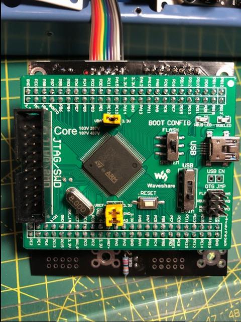
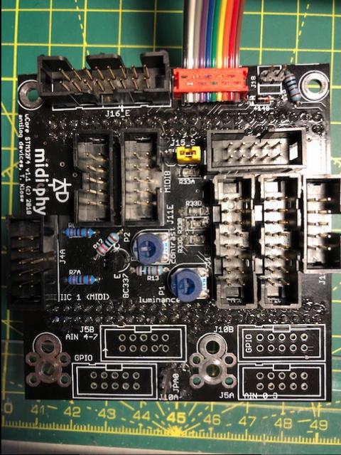
wild guess, but maybe bridged “E” lines? E.g. on the waveshare board headers? Could you upload hi-res photos of the front and backside of your wCore PCB? Have you pushed in the waveshare board all the way? The wCore with installed waveshare board must be able to stand on 20mm hex standoffs, if the assembly is higher, the waveshare board is not pushed in fully.
Many greets,
Peter
Thank you and … given the behaviour with the one screen being shared I’m going to guess at bridged ‘e’ lines and/or a config issue (the former most likely). I’m at work today and at an event tonight so I won’t get the chance to troubleshoot more until tomorrow evening… but I’ll have received my extra shipment of 5x2 headers and plugs by then so I can clean-up those cables as well.
I’m pretty sure the Wavemaker is seated as I’ve done it twice and my palms are a map of the cut pins on both sides as it’s a good friction fit!
- just to check on theJ15A/B pins, mine run top to bottom as I sit in front of the Seq… is pin 01 top-left, or bottom-right?
Thanks!
Sorry - ignore pins question above… I can see the notches on the schematic ![]()
Mirroring is very confusing. As you have identified the +5V (unused backlight) and +3v3 (OLED power supply, J15_S is correctly jumpered), you can orient yourself this way.
I don’t think I was clear before: with everything plugged in (power off), check for continuity between the two OLED headers, i.e., left OLED pin #1 with right OLED pin #1 and so on. Also check the adjacent pins within one header for shorts, especially on the enable lines.
Couldn’t resist some probing!
Plastic inserted between OLED pins and headers for surety (no difference, though).
Reflashed bootloader and ran LCD commands… that put some gibberish (some correct characters) on LCD#1 - ie. the problem one. Reflashed Seq and got something on LCD #1 on first boot but blank thereafter. Even with gibberish on LCD #1, LCD #2 was still swapping to display the actively parameters, as before.
Continuity as expected on all mirrored pins EXCEPT e pins. No connection there. I got a limited continuity beep (single pip, 0.303 on screen of DMM) for the adjacent pins to the top-right and top-left of J15A and B (as picture them below) - I think this is actually top left and right on the schematic. I’m jiggered if I can see a short, though! So not sure how to interpret this.
Images attached - can’t see any shorts/bridges under a loupe… I can reflow the board tomorrow, though.


Next two things to try: check that all required lines are correctly pulled up to 3v3. These are RW (R33A), E2/E1 (R33B/C) and RS (R33D, 560R). All of these pins should be at 3v3 when powered up. Always take care not to short pins together on the OLED when probing!
If you don’t have another cable/headers around, you could try to use the SD card one (J16E; the application should start without an SD card). You’ll probably have to bend the metal parts holding the display in to remove a cable.
It could also be worth tracing the signals back to the MCU pins.
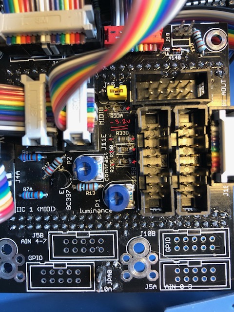
I’m getting some confusing (to me) readings here… images attached.
Measuring the noted resistors above, I’m getting -3.3v grounding on left/+ve on right, as per image.
On the headers, when I ground to Vs, I’m getting ~0.1 - 0.15v on both E, RW and RS pins.
Hmmm… have I measured this wrong? If not, how is the R/H OLED working?
I’ve already ruled out issues with the OLEDs/screens - either screen works perfectly when plugged as LCD#2 (R/H).
I’ve checked continuity between:
PC8/9 on the Wave board and the E pins in the headers (all good);
PC11 and the mirrored RW pins (all good);
PA8 and the RS pins - no continuity.
So… I reflowed R33D, got continuity between PA8 and RS thinking that I had the fix… and no change ![]()

I confess that I’m not 100% sure about how the driver works here. It could be that the data edges are positive-going, meaning the MCU pin drives low for most of the time. This you could probe with your scope.
As the displays work when plugged into the other J15, this would seemingly rule out problems with the OLED itself or cables. Meaning that it’s further upstream.
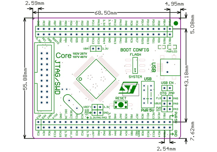
I would trace the E lines back to PC8 and PC9 on the v407 breakout (the header pins are labeled), and also back to the MCU pins. It could be that you have a weird contact on the female header for example.
https://www.waveshare.com/core407v.htm
https://www.waveshare.com/wiki/Core407V
https://www.waveshare.com/w/upload/5/58/CorexxxV-Schematic.pdf
Thanks!
I updated the post above with some continuity checks… but not as far back as the MCU so I’m doing that now.
Could you check the value/number written on R33D? It does look a bit like an initialisation error. Often this is to do with R33D, hence it is a lower resistance to make the pull-up “stiffer”.
Reflowing the resistor shouldn’t affect the connection between PA8 and the OLED. Hence it could be something like a cold solder joint or unintentional connection to 0V on R33D, or an intermittent contact on the female header.
Following on from the above, reflowing R33D has made changes.
I now DO have 3.3v on the headers at the E pins and RW pins… but still nothing at the RS pins. No short between E pins.
I’ve traced continuity all the way from the MCU pins to the headers.
STILL nothing on LCD #1!
R33D is labelled as 561 - tested (in situ, no power) at 531.5
R33D should be ok - please also check connectivity of all datalines - from the problematic J15 port to the waveshare board (through the headers) - some years ago, i had a display with similar garbage and one data line was disconnected.
You might also want to reflow the pins of the waveshare headers (on the wCore PCB) before measurements, just to try that out before you measure a lot of pins. If it still does not work after reflowing, measurement from J15 to the waveshare core MCU and then to the STM32F4 IC pins are the only way to check for continuity (quite some work!). Also check for “neighboring” unwanted shorts, as those could well cause the problem, too. I’d recommend to reflow every pin first, especially as reflowing on R33D seems to have helped!
Many greets,
Peter