TR606 CY+HH Kicad Shematic (Capacitor labeling on old shematics)

i draw the AOUT_LC

instead of using them single resistors, i tend to use smd resistor arrays: http://www.reichelt.de/4-Resistors-SMD-1206/BCN16-10K/3/index.html?&ACTION=3&LA=2&ARTICLE=42471&GROUPID=4495&artnr=BCN16+10K

should reduce work and space enormly.

Very difficult to solder! 4 resistors in 1206 package! 

I try to keep all of my SMT in 1206 and SOIC wherever possible. This makes it the most accessible for newbs.

https://www.conrad.de/de/widerstandsnetzwerk-100-smd-4816-112-w-2-100-ppmc-bourns-4816p-1-101lf-1-st-1055286.html

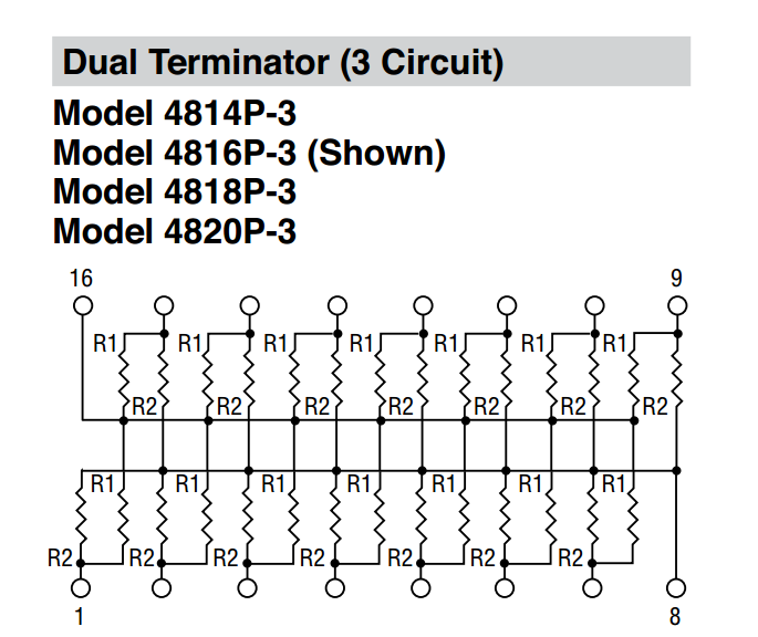
Is a resistor network with 2% tolerance, the package size is “small outline medium” with the same pitch as SOIC. More values available elsewhere (e.g. Mouser).

10k

https://www.conrad.de/de/widerstandsnetzwerk-10-k-smd-4816-112-w-2-100-ppmc-bourns-4816p-2-103lf-1-st-1055290.html

Yup , i’m ok with Latigid SMD Soldering isn’t the best DIY way. To save space,maybe mounting resistor vertically would help

 
vertical-mounted-resistor.png

but it ends up this way:

lc

solder 4 of those chips -with the size latigid mentioned, is not difficult, because it is a resistor it isnt that heat problematic. (the only problem is the conrad price)

bend, cut, hold, solder, cut 32 of single resistors is hell of boring work…

sure :smiley:
A resistor Array is much better in here , i talked without reading. my bad

Agreed, bent resistors suck, but you can place a 1206 in the same footprint.

Look at this network from the same series:


Might be interesting.


Hey that res networks sounds cool =)

Just now, latigid on said:

Look at this network from the same series:

complex - but not what aout_LC need…: aout-lc-scheme

-i think-

@Phatline : It really looks quite the same than in the schematic, at least to me  did not looked well . My bad once again.

@Phat You’re right, I don’t think it will work, sorry about that.

 I am coming back to the Accent Signal. Is it 15V Bipolar or not?

1 hour ago, Psykhaze said:

 I am coming back to the Accent Signal. Is it 15V Bipolar or not?

No it is in a Range from +4 to +15V (with the 4 i am not really sure), it simply feeds Q29 with Power -negative Polarity would not make sense-

  • the Base of Q29 is shortley triggered with the Trigger Signal - coming from Q28,

Q29 now switches thru for about 1ms - with the Accent-Voltage - coming from AOUT_LC … the other Stuff after Q29 are then is a Envelope. (as far i understand the circuit)


Sometimes some circuits are dealing with bipolar inputs by inverting the negative part, that’s why i asked . So it’s positive voltage feeding but not from zero and up to +15V.
Thanks you for this precision =)

here is the list of parameters for the HH+CY Frontpanel, maybe add 3 trigger LEDs?

1 Like

oh cool ! I was in the wiki but i’m going in illustrator right now :stuck_out_tongue:

Also , good ideas about LEDs!
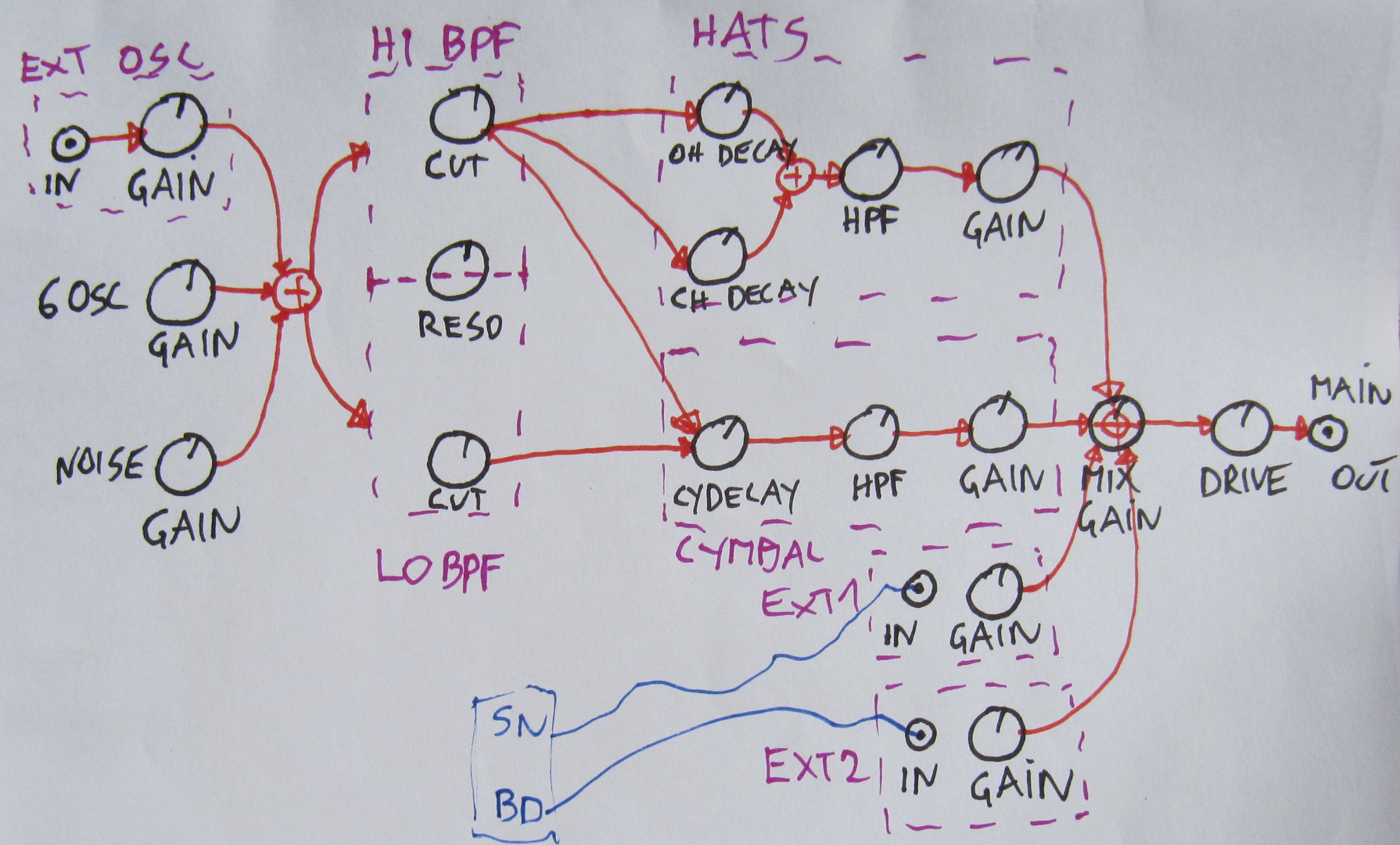
About the mixed output, i think it would be good to have separated output for each part (HH/OH/CYM/BD/SD) in addition of the mixed one 

Edit : I would keep SD/BD in plugs internal and Gain pots on its specific panel

1 Like

agree with SD and BD Plugs and Gain.

i would preefer Trigger LED located near Decay Pots (because the trigger is a envelope thing)

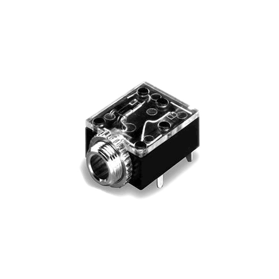
individual outs > ok > so we need special plugs, which cut the conection to the mix bus - i know that most 6,3er Plugs can handle that, do you  a 3,5er plug which can handle this?

you mean something like that ? :

yes but the slot should be mooved to 90° (standing)