thanks Wilhelm! Much appreciated - I think I probably blew my screen as well, so am going to try ordering a replacement that doesn’t require the rewiring, but if I decide I must have the white on black in the future this might come in very handy!
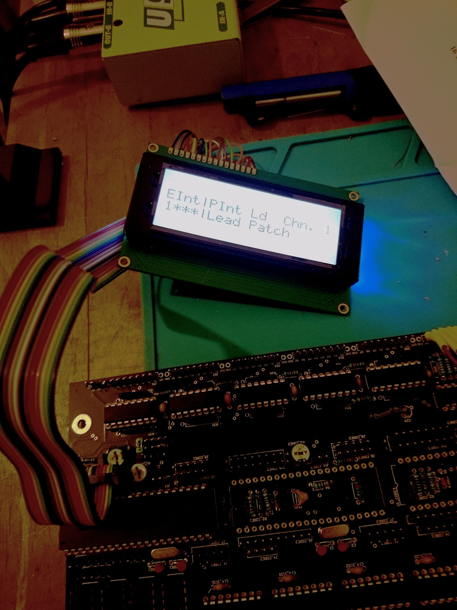
Congrats! I remember that moment when I finally got a legible message on my screen ![]() all downhill from here.
all downhill from here.
1 Like
hmmm, I’m on the point of actually putting some SIDs in… unfortunately it seems like the colour change LEDS are maybe not going to work… or at least not properly!
the ones in the Matrix seem to do three colours, rather than cycle all of them.
the other LEDs are staying resolutely red… not quite sure what’s going on here.
Have tried 1k/220 and a resistor leg bridge… the lower the resistance the more the matrix seems to change colour, but it’s still not right. Using resistor legs seems to mess with the LCD so that it displays random characters, which doesn’t sound brilliant… bit more exploring to do I guess… shame if they are going to stay red forever!
Do you have a datasheet on the color-cycling LEDs?
If a LED is matrix-driven with 1/8th duty cycle, that means on - off - off - off - off - off - off - off -on - off - … - so they might actually reset their color cycling because they are powered up all the time again?
Many greets,
Peter
ok, so something even weirder now…
Sometimes it doesn’t boot up MIOS, but it does do a pretty thrilling light show. I assume it should not do what it is doing in video 1 in the below instagram post?
When this happens (usually when it’s been turned off a while, it never seems to boot. Then a quick restart or two will make it do what happens in video 2…
Is video 2 a bit closer to what is supposed to happen when you turn it on?
I also seem to be getting some slightly weird LCD screen stuff going on
Do you think this might be fried Shift registers from the LCD incident? I think maybe I have to try replacing them anyway… ho hum…
Still, the light show is nice!
<___base_url___>/?app=core&module=system&controller=embed&url=https%3A%2F%2Fwww.instagram.com%2Fp%2FBrLoGu1HZX3%2F
Will try and find the data sheet - are both sets of leds matrixed that way? I did wonder if that was why the selection leds were not changing - they are slow change so maybe get reset before they can change. Annoying, but not the end of the world I guess. The matrix ones are fast change, and they seem to be working in some ways when MIOS is running. No idea what the fancy light show is about! Kinda odd.
Going to try switching out the shift registers first I think, unless I can think of a better idea!
The second video looks more or less correct. Hard to tell exactly because of the bright LEDs and otherwise dark video, but it should definitely start up with a quick light show on the matrix. IIRC, the boot-up lightshow has two stages, one with the LEDs in a more-or-less randomly flashing pattern, and one where the LEDs alternate a checkerboard pattern—I forget which comes first.
You have the new Step E power circuit, right, with the sVreg? I had a little trouble with excess power draw on start-up causing issues with my boot up, but it was solved IIRC by changing to a smaller cap on the input of the sVreg. Might be a similar issue if your fancy LEDs draw too much current?
It doesn’t seem like the shift registers are the problem, as least from what little I’ve seen in those videos.
My bad, it was too big of a capacitor on the output of the sVreg, coupled with too much current draw on start-up.
ah, thanks - so the cap at C3?
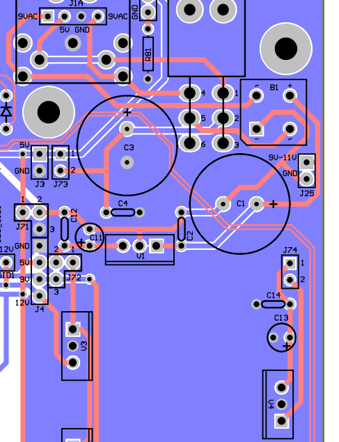
Pretty sure I only have 10uf in there already, can I go even smaller? It’s just smoothing the already regulated 5V right?
Do you remember what you used, or did you mean you’d changed it to 10uf? I wonder if it can go even lower, sounds from your thread here that it isn’t actually doing very much…>
< base_url >/topic/20363-mb-6582-current-draw/?do=embed&page=2
thanks for the help.
I guess it might be the current draw is just too big. Although it does start up sometimes - both this and the screen misbehaving seem worse when all the LEDs are connected.
I think Hawkeye is probably right about the slow cycle LEDS being retriggered too often to colour change.
So I guess I will see if I can get it to reliably start up with the colour change LEDs in before thinking about changing all the slow ones for fast ones!
I guess I might try some bigger resistors and see if I can get the current draw down..
I forget exactly what I put in there, probably a 10uF. It’s probably not even necessary tbh. Otoh, I don’t think the capacitor is your problem, especially if you only put in a 10uF.
Something related to current draw seems likely though, since it seems like your main deviation from a typical build are those LEDs.
Did you socket your current limiting resistors? You could try pulling those and seeing if you get a consistent good boot up. If you didn’t socket them, you could cut/desolder the board connections that go with the LEDs, or if you wanted to try bigger resistors anyway, just clip them.
thanks - yeah, I have sockets for the resistors. have tried a few combinations now - the fast changes in the matrix get through all the colours only when they are about 150R… any higher and they don’t operate very well, if the resistance gets high enough they just stay red, which I guess suggests they are probably drawing a lot of current to do the change..
There seems to be another issue as well though, as sometimes it starts and sometimes it doesn’t and it feels like some of that is maybe to do with a loose connection/shorting in the cables joining the two halves. I can’t shut the lid the way it is at the moment anyway, so need to give that some attention and remove it from the possible causes!
Hoping not to have to start the control surface again, but not sure I am going to avoid it if I can’t get all the LEDs on without fritzing the LCD or the buttons or something!.. desoldering 100 LEDs may not go perfectly I am guessing!
Also: there should be more than one patch in the memory banks on start up right? Something seems to be awry there too…
Random restarts (or the unit sometimes not starting up) remind me of a 5V rail problem i had early on, back then still with the original C64 PSU.
The current draw on 5V (using a VFD) was just too high and it went under 4.7V or so on the 5V rail, the PSU was overloaded.
So, which PSU are you using and can you measure your 5V rail voltage during operation?
Patches need to be uploaded with a Sysex transfer, so all should be good there as long as you can access all banks.
Many greets and good luck!
Peter
ah, great, thanks - didn’t realise that about the patches
Am using PSU Option “E” from this thread:
http://discourse.midibox.org/t/topic/19867
so the 5v rail is coming from this - RECOM POWER R-78B5.0-1.5L SWITCHING REGULATOR, 5V, 1.5A
I’m just trying to desolder the connections from the CB to the base as the way I had attached them did not leave room for the case to shut. Once I have had chance to reconnect them i will take some voltage measurements and see what’s happening to the 5v rail.
There are no SIDs at all in at the moment, and only three PICs, so if it is insufficient current it might be quite an issue to deal with.. but then is there any reason I couldn’t use a larger switching regulator?
Say this?
https://uk.rs-online.com/web/p/switching-regulators/1392821/
i’m not all that learned about power supplies tbh… would this have knock on effects on the capacitors required? I think not… just wondering if anyone sees any obstacle!
Before you order a new regulator, run some tests, find it if your current regulator is drooping, measure current draw with and without LEDs, etc.
will do, sadly don’t think I’ll get to it until the weekend, but will get to it.
Was just wondering out loud if there might be a way round it if this turns out to be the issue…
thanks for all the help. Sort of wish I’d just used normal LEDs now, but we’ll see!
Hi… hope you don’t mind me asking
now have everything plugged back in.
have been testing voltage at JD9 and this seems to be 5v regardless of whether the control surface is connected. Is there somewhere else I should be testing the voltage? Also, where would you suggest testing current load? I’m not quite sure where in the circuit to put the multimeter.
With no Control surface connections made at all, everything seems fine. I can plug in up to JD6 working right to left, and nothing seems amiss - LCD still displays correctly, etc.
When I plug in JD7 there is a flickering character on the LCD occasionally… so that’s worrying.
When I plug in JD8, this is where the problems really begin. The LCD starts showing distorted text, extra characters etc. The Matrix lights up, but when you select a point on the matrix it seems to leave “trails” of light leading up to the point, or just display random lights.
I am wondering if the transistors here might have been damaged somehow… I assume they are controlling the LED matrix. I don’t really see how that affects the LCD - maybe it is a power issue.
thanks in advance for any advice!
it seems to boot up every time fine since I rewired all the CS connections (and got the right resistor values) though…
well, it now has 2A on the 5v rail and the same issue persists…hmm, I guess it’s worth desoldering the transistors and replacing before I desolder and replace 100 LEDs!
tried the "make all the LEDs light up test from the WIKI. everything lights up fine… no colour changing, but the fast change ones actually look a different colour depending on viewing angles, which is very odd. column 7 is a slightly different colour to the rest…
can’t really work out what is happening here… I see some desoldering in my future though…
Having read some of the manual I am also not convinced the buttons are all doing what they should in MidiboxSid…
If you’re getting 5V at JD9 then that rail isn’t sagging.
Before measuring current, make sure you know how. Don’t mean to offend if you already know, but it’s very important if you don’t. If you try to measure it like current, you’ll short 5V to ground and likely fry something. (Also, make sure to change your meter *back* to voltage mode before using it again; made that mistake on my TTSH.)
Anyway, I think there’s a header you can measure current from. You would have to break the circuit (take out a jumper) from the 5V regulator and the rest of the 5V rail and insert the meter in series.
If I’m being totally honest, at this point I would admit defeat and install regular LEDs. The fact that your issues start as you plug in parts of the LED matrix and only get worse as you plug in more of the LEDs seems to implicate the LEDs pretty strongly. I’ll be damned if I really understand *why*, but the LEDs do seem to be the factor that differentiates your build from everyone else’s. They’re complex little devices compared to vanilla LEDs.
I haven’t looked very closely at how the LED matrix on the Mb-6582 works, to be totally honest. It certainly can’t hurt to swap out the transistors if you have spares handy, but at this point I don’t particularly suspect them. Sometimes it’s better to try the easier fix before the difficult fix just in case.