The LCD wont show anything (except maybe a series of squares where the characters are supposed to be) without the PIC. Or did you mean that the backlight wont turn on?
I would just go ahead and burn the PICs. You will be able to tell if it worked when you connect to mios on your PC via MIDI.
unfortunately there’s no sign of life from the LCD at all.no backlight at all.
After a bit of messing about in theory have MIOS and the mb6582 software installed on a pic, but still no sign of life from the LCD…
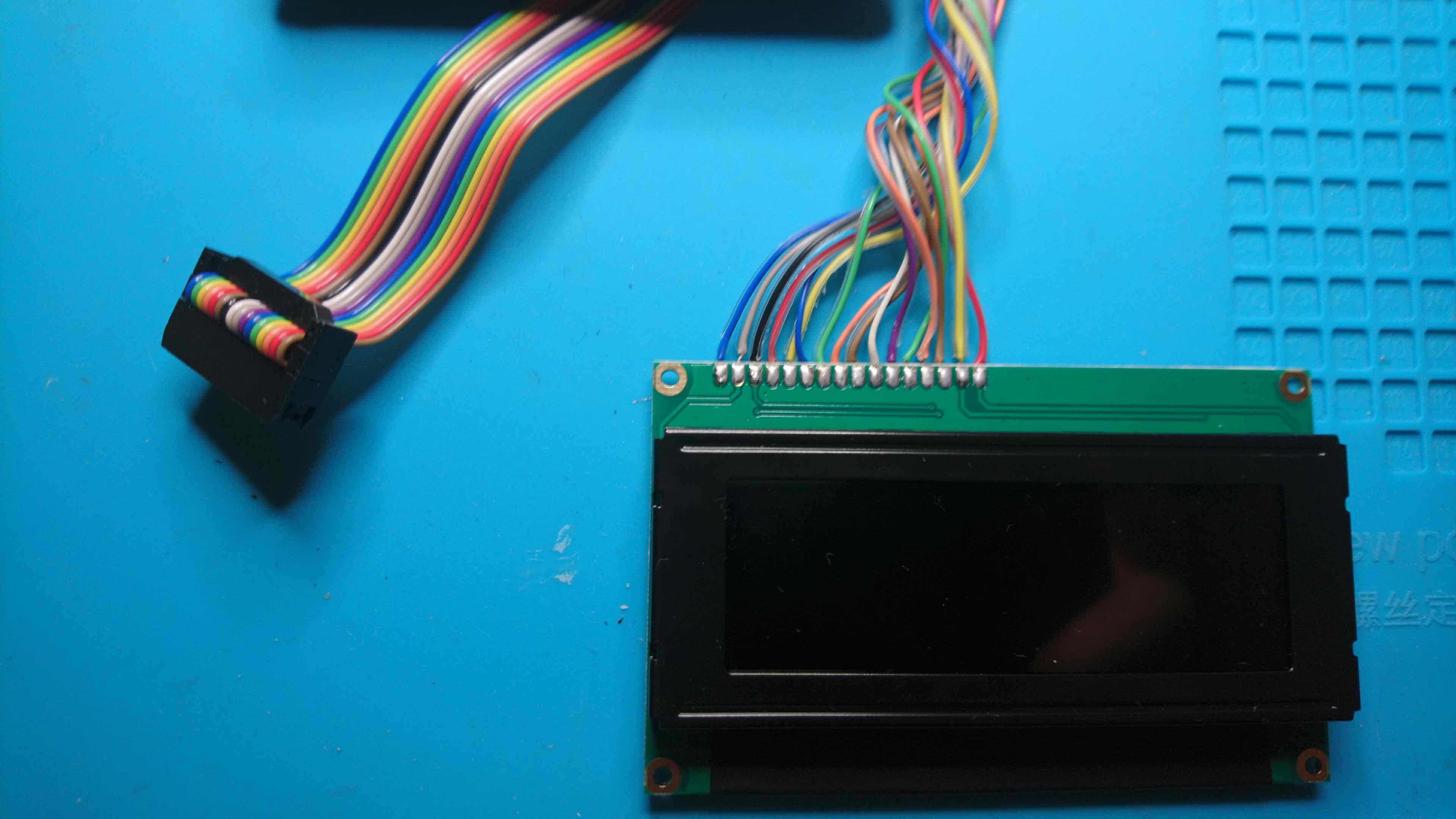
Can I ask - is your screen a Midas? Just looking at your wiring in the pic above and pins 15/16 look reversed compared to mine…
also, the pins on the board are labelled “1” and “9”, but from what everything suggests I think those pins are 1 & 2? is that correct? if this is the case, pins 2& 3 seem to be shorted by the pcb… not sure that’s correct!
I think the backlight should turn on even without a PIC. Is everything else on the board populated? (Thinking specifically about the display trimmers.)
The LCD wiring is confusing and was one of my more troublesome spots. I managed to wire it up backwards (or upside down…or something) even after double- and triple-checking my work.
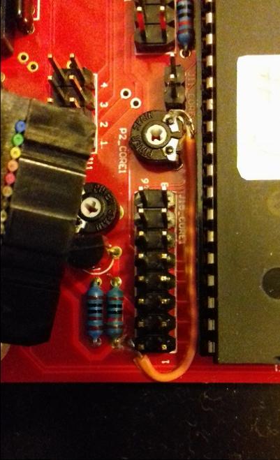
Can you do me a favor and post a picture of your wiring and links to whatever documentation you’re working off of? I’m trying to figure out what you mean with the pin numbering (and the more general issue of it not working, of course).
oh, those two pins should absolutely be touching, but with a 10k resistor, not a 10R…
have replaced and lcd still not working, but i guess maybe i blew the transistor T1 as well. and/or the screen… in theory if i give the screen ground and 5v for the backlight that should work on its own I guess?
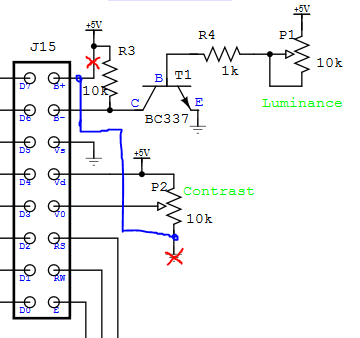
Hm, I vaguely recall being confused by the pin numbering as well. In any case, the guide you linked to should be correct, as J15 has the same pinout on MB6582 as it does on a normal core (where the pins aren’t labeled, fwiw).
thanks - that suggests I’ve probably blown something or done some dodgy soldering I guess!
If the LCD backlight should work as soon as it has power, will test just those two pins with a separate power supply first and make sure I didn’t kill the screen.
Then I guess triple check the screen wiring/contrast pots/transistor
tbh I am pretty sure I have the wiring right at this stage, so maybe I messed up elsewhere…
sounds like maybe the backlight polarity was reversed? can’t tell from that really if it was just the backlight or the whole wiring though…
Stuck at work now, but going to try just powering the backlight both ways when I get home.
Because it’s a negative screen it might just look completely blank/dead with the backlight off, maybe it’s fine… I hope anyway <fingers crossed>
My issue was that the entire cable was connected backwards at the LCD end. I still got some functionality because both sides (pins 1&2 and 15&16) are power (one side for the actual LCD and one side for the backlight) so everything was in fact receiving power, but nothing else was connected correctly. I am pretty sure this isn’t your issue.
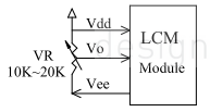
Looking over your display’s data sheet (specifically the pinout), it seems like maybe your display needs a negative voltage reference for the backlight to function? This issue is described in the LCD troubleshooting document (http://www.midibox.org/dokuwiki/doku.php?id=troubleshooting_lcd_displays) but unfortunately the solution is not described there: it only gives a dead link.
thanks… and I was wondering about the negative voltage bit…
Need to decide how wedded to White on Black I am I guess and maybe get a different lcd if I can’t work it out…
I am still a bit confused as to what pins 15 & 16 do though?
do you think it is it expecting -5V dc at 15 or 16? And what does the other one get?
the tech spec seems to show an optional “negative voltage generator” providing negative voltage from Vee, almost as if I just need to hook pin 15 to pin 16… that can’t be it though surely?
Okay, double-reading the data sheet and I don’t think it needs negative voltage for the backlight. But pin 15 seems to be used for something other than powering the backlight, which is odd. According to the data sheet, it supplies negative voltage as part of an external contrast adjustment circuit.
The backlight seems to run on normal +5V running into A (+) and K (gnd)…but I can’t figure out where pin A is supposed to be from the pinout in the datasheet.
I’m guessing the LCD itself doesn’t have any more helpful labels or anything, just pins 1 and 16 marked probably?
edit: I think the backlight power is connected internally somewhere, as opposed to needing a separate supply.
that’s where I was arriving as well at looking at the sheet - pin 15 is out from the negative voltage generator.
tbh I might just order a white on black version, which appears to be the right configuration rather than try and mess around too much…
thanks for helping I would have just had suspicions about it, but you kinda confirmed what I was thinking.
edit: I think the backlight power is connected internally somewhere, as opposed to needing a separate supply.
I was wondering this. So I could in theory skip that pin, but then I think it still needs the contrast circuit… I think another screen is going to be easier.
I’m pretty sure you want to leave Pin 15 disconnected. Seems like a bad idea to be injecting negative voltages into your MIDIbox. But I’m not sure that having it connected would be enough to keep your backlight from turning on, as that seems to rely solely on proper voltage at Pin 1 and Pin 16, which you should have.
So I would disconnect the LCD entirely and double check that all your voltages are still correct (ie double checking that nothing went wonky from applying -5V to pin 4 of J15). If that looks good, snip the wire attached to Pin 15 and see if anything changes.
Disclaimer: We’re already a bit beyond my full understanding, so consider these comments as rough guesses rather than truth. Still, this is more or less what I would be doing to troubleshoot.
You may be able to get contrast working with a jumper wire from pin 15 to the contrast trimmer (and cutting a trace on the board), or it might work as-is with the ideal setting all the way to one end of the trimmer’s range instead of somewhere in the middle, but tbh if it were me, I would certainly be tempted to just get a different LCD.
thanks - pretty sure, I can live with a black on white screen, so am going to order one now I think. I’m sure it’s possible to mod it to work, but I’m worried enough about it all working properly anyway tbh!
fingers crossed I didn’t fry anything except the resistor I already replaced.
not sure I hold out much hope for the transistor in the contrast circuit!