Short answer: trust the MIDIbox build docs. It’s supposed to be a 22nF cap.
Long answer: it’s fine to experiment with different values and types of caps. You should be socketing this cap anyway so that you can easily install 6581 chips at some point in the future, but that also makes it easy to experiment with different caps and see what sounds best to your ears. There are also a couple values in the MB SID firmware that let you calibrate the filter response. IIRC, you can adjust the response range as well as choosing either linear or log response (the latter depends more on which SID chip you have, but go ahead and try both to get an idea of the difference).
Back to short answer: just stick with the recommended 22nF caps. The SID filter is never gonna be stunning or full of character, and the 22nF caps are known to work well.
thanks, that’s what I figured… just thought I’d be 100% on it.
I suspect this might be the explanation for some slightly odd filter behaviour on another project I tried out before deciding on this… I’ll never get that time back!
Another quick Q… hope no-one minds the questions! - has anyone got the passive mixed output from J70 hooked up, and if so what resistors did you end up using for a decent output level?
Ask all the questions you like! Not like this forum is super busy anyway.
I’m away from my synths at the moment, but I have a Mix Out jack wired up. IIRC, I used 10k resistors (pretty standard for passive mixing), but I’d have to double check that. I use the mix jack almost exclusively and I haven’t noticed any issues with output level.
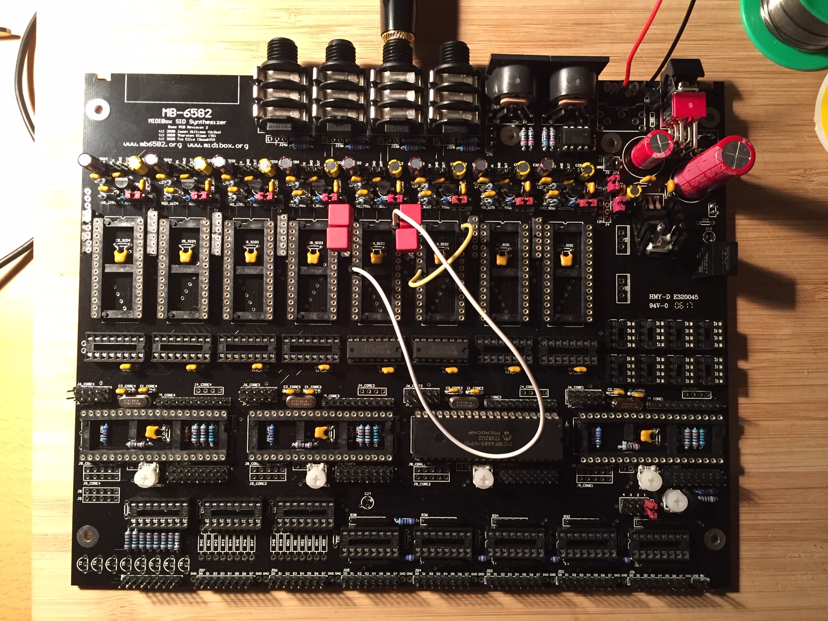
Working along slowly but surely here. Soon finished with the main board. Passed all the tests without any major setbacks so far. Just managed to get some first sounds out of the SID.
The 10 uF electrolytic caps I got were way too big and the film caps are a bit bulky (as you can see). Luckily I had some electrolytics lying around.
p.s. sorry for the thread hijacking, but it seemed easier to keep it in one place while we’re both building!
I actually started with the control surface… which I think is probably the “wrong” way round… but seemed easier.
Just need to get the LEDs in now and will be finished with that board.
also - @HybrisBehemoth - what solution are you going with to power it?
I am pretty sure option E “one PSU” is the right choice, but I can’t decide if it makes sense to fool around with a 7 pin DIN and cutting the lead off a 12V PSU… or maybe laser cutting some kind of acrylic disc for the case so it can just be a normal barrel jack plug and can use a normal PSU…
No worries about using the thread. As you wrote; since we’re both building.
I did PSU option E, which seems to be working well so far. All the guides found here has been super useful! I’m planing to use a standard 2.1 jack. The only problem is that my panels have the big 17mm hole for the DIN-jack. Has anybody found a nice solution for this? The disc-solution came to mind for me as well. But I haven’t looked in to it further.
I like the multi-coloured-legos kind of look to the knobs! Are you going to do those colour changing LEDs as well?
I’m going to try the colour change LEDs… and cross my fingers it’s not totally stupid once it’s finished! Glad the knobs look OK.. they cost a few quid
I was planning on a standard barrel jack too - but I’m wavering a bit now. It feels like either way needs a bit of a bodge, although I guess the barrel jack at least means you can use any spare wall wart, rather than having to solder a new one.
My plan was originally to laser cut an 19mm disc with a 2mm lip and a hole in the centre for a panel mounted jack and glue that into the panel. I in theory at least have access to a laser cutter at my local makerspace… haven’t actually cut anything yet though!
thanks, and thank you for the control surface tutorial, really does make it so much easier and answers so many questions!
I was still VERY nervous the JB Weld stage would mess up, was pleasantly surprised when it all seemed to be solidly glued in place!
I think my front panel is very slightly bent though, which is going to make getting all the leds through it in one piece quite interesting. Hoping I may be able to screw the screen in and only have to do it once…
I had originally planned on a standard barrel jack for power. I ended up going with the 7-pin DIN for a few reasons.
Probably the main reason is that the header pads for a panel-mounted power jack are close enough to the edge of the board that they kind of interfere with placing a panelmount jack at the same location. You might be able to get around this by placing the jack higher up on the rear panel or elsewhere on the panel altogether, by using angled headers instead of straight, or by simply wiring the jack directly to the board (though this list option will make servicing in the future more difficult).
The above hurdle could have probably been surmounted, but lo and behold, a 7-pin DIN connector randomly fell into my lap. I had been asking around for a source on the OG power switch, and a kind forum member hacked off a piece of original C64 PCB for me that contained both the DIN jack and the switch. Obviously this won’t be the case for y’all, but having the part in hand made the decision a bit tougher.
Other, minor reasons I went with the DIN jack: no need to redesign that part of the panel (I had custom panels made but I didn’t want to change any more than I had to), and no possibility of using the wrong voltage/polarity power adapter ever.
Attaching the new jack to a power adapter was really easy; don’t let that be the only reason you shy away from the DIN connector.
That all said, if the part hadn’t magically appeared for me like that, I’d have probably figured out how to use a barrel jack. I’m afraid I can’t advise on how to adapt the DIN sized hole to a barrel jack though, that’s a tough one. I had planned on custom panels from the beginning.
Pictures are working now, looks good! Those filter caps are a little hilariously big, lol.
And I love the rainbow knobs on the other synth! Reminds me of the original C64 marketing logos. I wanted to do something similar, but it’s relegated to just the feedback knobs around back.
Just looking at the details on programming your own PIC chips… didn’t realise I needed to build an adapter board!
Is this still the correct info on doing this? Seems like there’s not much other option, so I had just ordered a Pickit 3 and 40 pin programming adaptor off ebay, but I guess the adaptor was a waste of money… d’oh!
I suppose it’s not too much bother to solder a little board to program the chip…
possibly a silly question, but just in case anyone’s around…
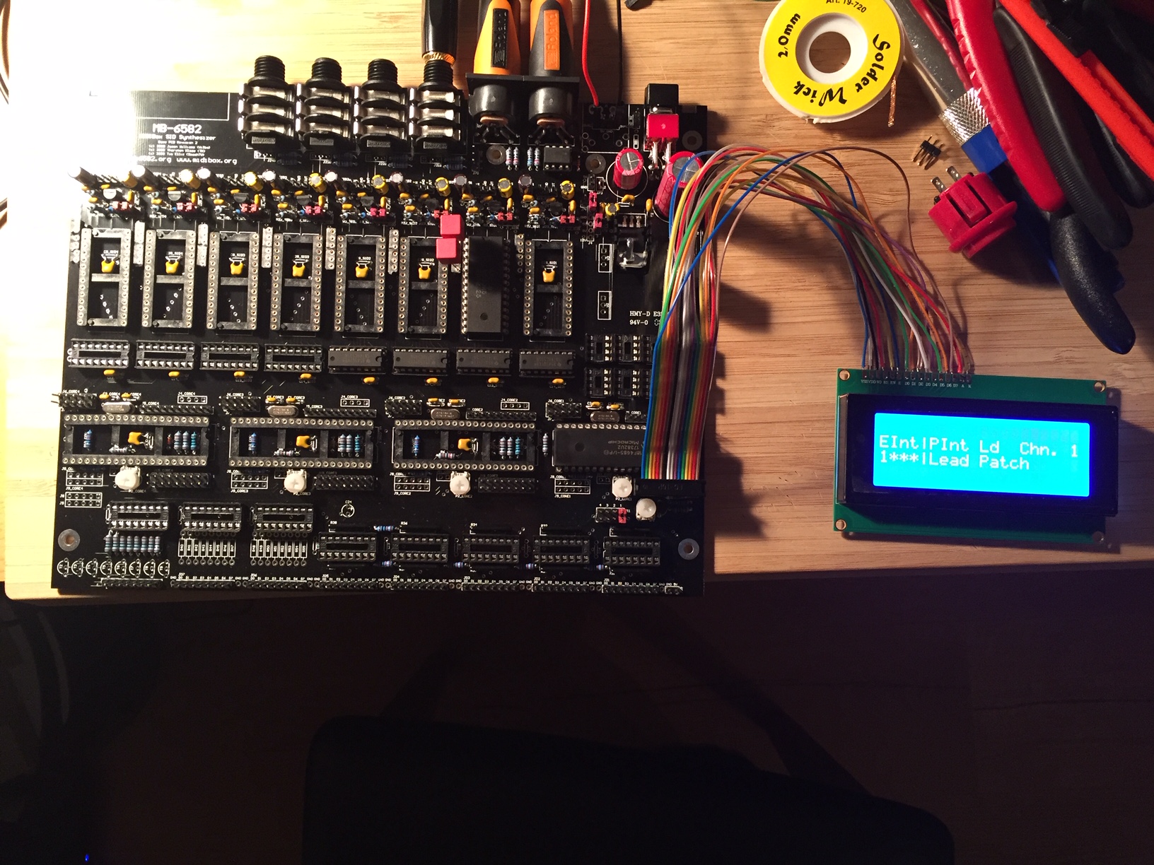
Should my LCD power up/show something with no cores in the board?
I sort of expected yes, but it doesn’t even though there appear to be the right voltages and i have rechecked all wiring. Does it need a data signal of some kind to turn out? Just about to try burning MIOS in but if my LCD doesn’t work I have no means to tell if it works or not as I ordered the wrong audio outs as well and am waiting for replacements!
")