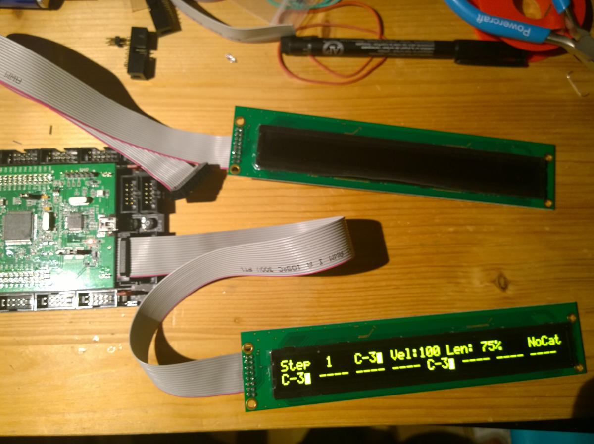
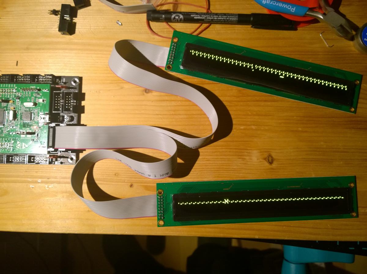
When I connect them both, I get random characters/dots. If I connect only one of them, no matter which slot (J15A/B), they display the appropriate content (left/right display stuff).
I tried swapping displays and cables, all is fine, it’s just that they don’t run/initialize? together.
When browsing the forum earlier, I have the vague feeling that somebody already had similar issue but I’m not able to find that thread again.
Can somebody please give me a hint what to check? Thanks in advance.
it involved a bit of driver hacking (changed 8bit access mode to 4bit mode, which helped, and separated the control lines, which i nowadays think was not necessary, but you learn ;-))
One ribbon solution was just desperate idea of desperate man who has no idea about LCD hacking
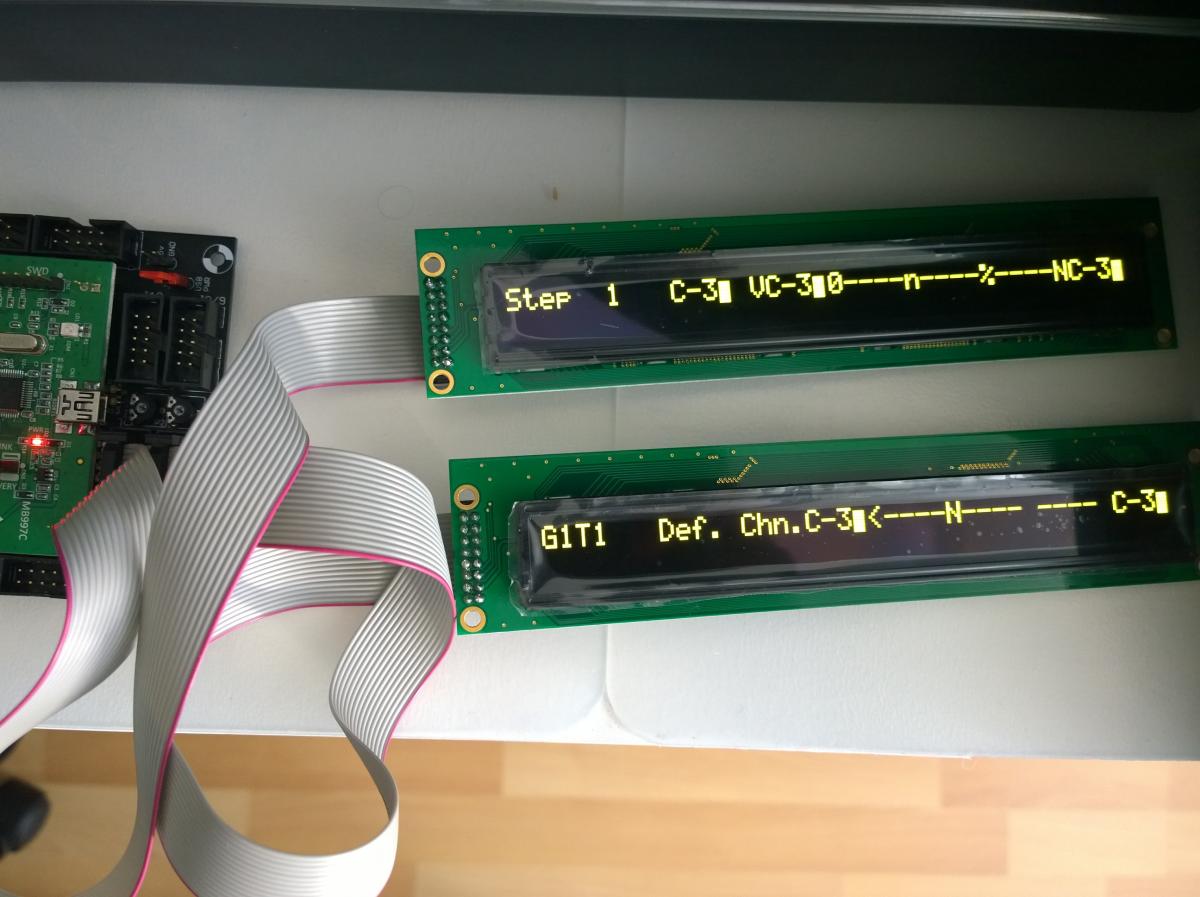
I made a little progress … sort of. I’ve changed the lcd_type to CLCD_DOG with bootloader update app and now the two displays show their content but only in first row. Content looks like smacked together, like two lines in one resulting in a bit chaotic stuff. Forcing the lcd_width/height has no effect doesn’t help.
Are you positive, that the OLEDs are exactly of the same brand and firmware revision as jbdivers?
I’m sure it’s the same brand and model, Raystar doesn’t have any other 40x2 OLED display. Bought it even from the same store (TME Poland). But I can’t speak of the FW revision.
if you´ll send me two for permanent testing, i could try to hack the driver!
.
.
.
…was just joking!
I´d love to build another SEQ with those displays later on that year, but it will take while - hope you manage to find the problem, if not, and no one else has ideas, i´d order two of them, too, to test. Later on :-).
edit:
it is probably timing related, as with many OLEDs, they could also have changed it from one firmware revision to the next - if you want to experiment, look into the mios32 repository /trunk/modules/app_lcd/universal/app_lcd.c and experiment with all timing specific code, e.g. look for delay_ctr and adjust the loop limits.
!!! There could be differences between LPC17 and STM32F4, as the latter board is faster, and this would explain why it works for jbdiver!
Some internal loops expect fixed runtime behaviour, like 4uS @ 72mHz - play around in app_lcd.c, line 474 and following. Good luck!
You could also test-swap the core for a LPC17 and see if that helps, if the theory is true, the displays are identical, only the timing code behaves differently on the different cores.
Cool! TK., when you have them in hand, would you have a look at the timing? It might be, that because the STM32F4 is faster than the LPC17, the number of waitcycles is not sufficient anymore - and that causes the phenomenon, that it works for jbdiver (LPC17) and not for cube48 (STM32F4).
same behaviour at my side when OLEDs connected to a STM32F4 core
OLED was working when I connected a common LCD to J15B instead of the second OLED
both OLEDs are working together on a LPC17 core
In the app_lcd driver I found the difference between STM32F4 and LPC17: for LPC17 the pins which drive E/RW/RS are always configured in Push-Pull (PP) mode, for STM32F4 these pins are configured for Open-Drain mode (they are pulled to the LCD voltage with external pull-up resistors).
The LPC17 variant was actually a workaround for a weakness in the LPC17 microcontroller.
However, I added a new CLCD type “CLCD_PP” which will configure the pins in Push-Pull mode instead of Open Drain
Observations:
OLEDs still failing at 5V LCD voltage
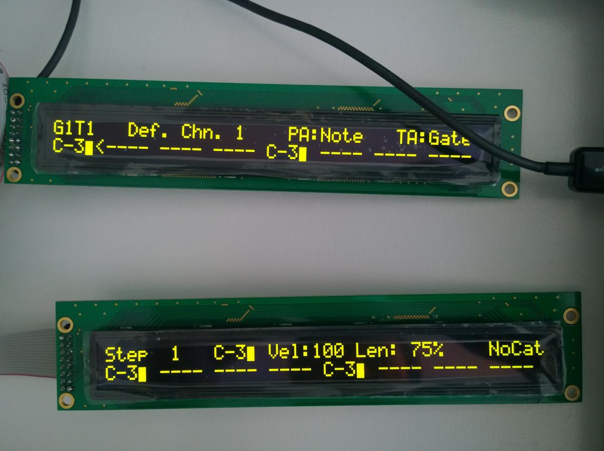
but OLEDs are working at 3.3V LCD voltage!
-> solution found!
And an explanation as well: the datasheet specifies an VIH (input high) level of 0.9 * VDD, which can’t be achieved via the pull-up resistors when more than one OLED is connected to the same pin.
By reducing VDD to 3.3V, and setting the pins in the “stronger” push-pull mode, the spec isn’t violated anymore accordingly displays are working properly.
@cube48: I will send back the OLEDs tomorrow, you may receive them saturday - be prepared for a nice weekend!
The new CLCD_PP type has to be configured in the bootloader with “set lcd_type CLCD_PP”.
As long as no new bootloader has been released, you can also set it with “set lcd_type 0x02”, which has the same effect.
In addition, you will need a new MBSEQ V4 release which will be available saturday as well - maybe together with the screen saver
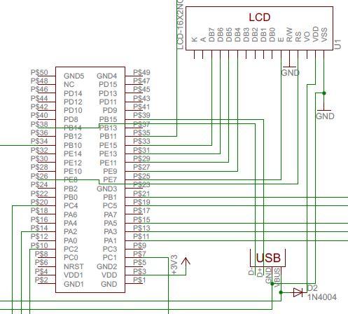
I’m just reading this topic. I had the same issue in an earlier, not MB related project with Raystar OLED (4*20) and F4Discovery. The solution was to lower the 5V VDD of OLED by a diode. It could be an alternative solution if the 3.3V regulator on the core was overloaded. And this OLED is for 5V VDD according to the type number. Attached a part of my schematics.
Anyway these Raystars are really cool LCD alternatives.
Ahh … I didn’t see that option in basic editor when I searched for it before, not noticing I was in ‘basic’ edit mode. But it’s possible in ‘full’ editor. Thanks for a hint.