Hi, I just finished the euroceiver module and like to test if it functions with the led etc. Is it already possible to test the module because when i put the usb in there i don’t see the led going on while the led is good while checking with a multimeter. Thanks, niels
Jumper setting is the same as in hawkeyes video. Just wanted to test the module only with the usb power but do you also need to supply power by the eurorack psu rail? Sorry still really noob with eurorack, this is my beginning with it i thought powering only by usb is enough.
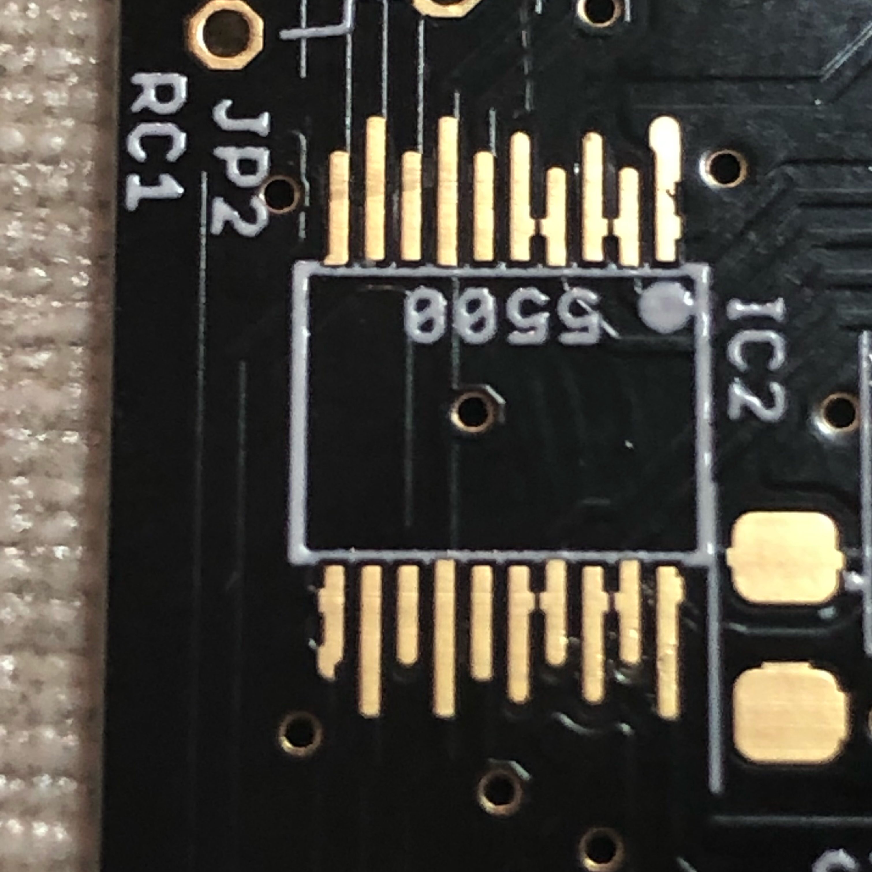
I like to start with the dacs but looking at the pcb’s i see that the bridges are really close to eachother. Is this normal? I Guess using flux will not solder a bridge but just asking
These pins are intentionally bridged; see also http://ucapps.de/mbhp/mbhp_aout.pdf (amplifier circuits now a bit different and available on the transmute8 page). The next run of PCBs will indicate this a bit clearer. On the plus side, no need to unbridge these if there’s too much solder!
Hi, another question. I am also busy with the matched resistors and looking at peters video he uses auto range on his multimeter to get 2 decimals. Whatever i try with my fluke 87iii i always get 1 decimal. How are you getting 2 decimals when measuring the resistors? I Guess it should work with a fluke right? Maybe not the right question for this board but since you are far better with electronics then me maybe you can help me. Cheers niels
Try to hold the yellow backlight button down for a second or so. At least this is how it works for my 87V meter.
Thanks man! works with the 87iii as well . Still trying to get an accurate reading every time because when I try several times I still get some difference of 0.01
0.01kOhm = 0.02% of 50kOhm, so pretty well matched already. Probably the offset current of the TL074 has a larger effect, but still it is nice to try and match as best as you can. Plus, we will calibrate each analogue channel on the SEQ individually.
Hi,
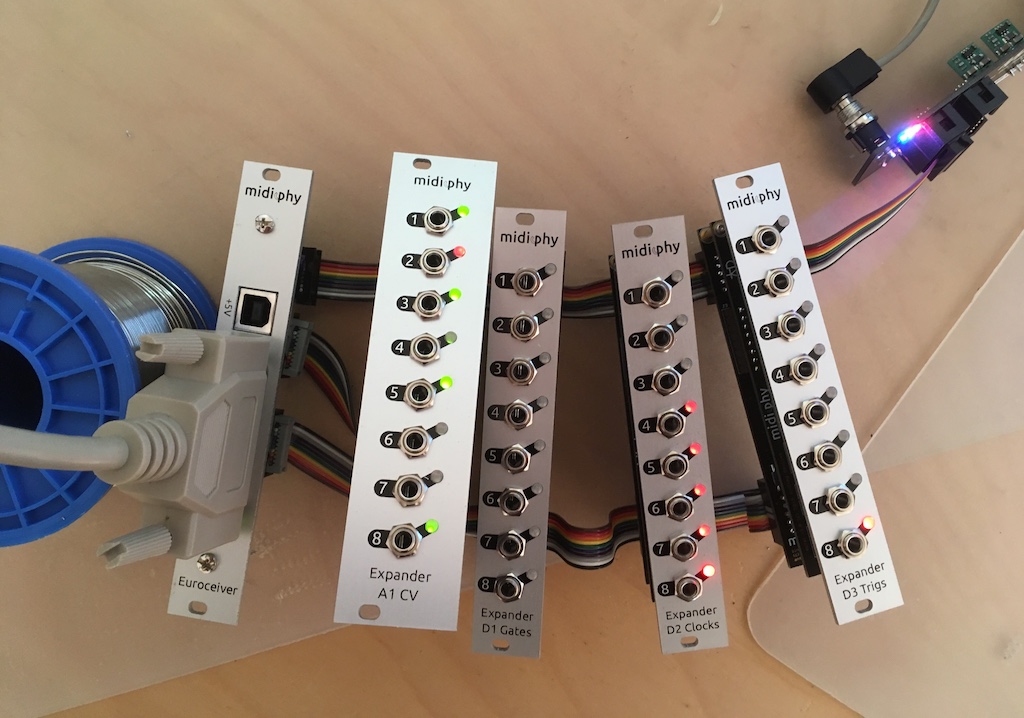
I finished building the boards and like to test them out. I order a eurorack case and psu but i did not receive them yet.
Is it possible to power all the boards with the usb power. I tried it but didn’t get any Lights on the other boards. Peters video and other screens only show eurorack power so i am in doubt.
Cheers Niels
Hi Niels, you would need some sort of +/-12V power supply for the modules. Do you have any old 12V wall warts or other PSUs around? You might be able to rig up something.
Hi Niels, you would need some sort of +/-12V power supply for the modules. Do you have any old 12V wall warts or other PSUs around? You might be able to rig up something.
Best,
Andy
Hi Andy, nice to know, i will make something in the meantime . What exactly is the use of the usb power on the first board?
The SRIO (J8/9) and J19 SPI require some sort of +5V, the source of which is selected by J5 (or SJ5). So the USB (power only) can be one of those sources, otherwise it can be regulated down from the Eurorack +12V or passed through the DB-25 cable, though I don’t recommend the latter as the wires are quite thin and there will probably be a voltage drop.