Has anyone tested out the tracking on these yet? Are they better/worse than previous version of mbcv modules?
recently TK. came over for a visit, for a long walk and also to grab his new set of these modules! We performed a tracking test in conjunction with a purely digital oscillator on a MIDI controlled synth and could not really hear any problem at all over many octaves. That is, if you perform good calibration, which is explained in the video tutorial in chapter 64, here: https://www.youtube.com/watch?v=dD8VeSuTKWI&t=5561s
Hi,
I installed all the modules and like to calibrate but when i power on the a1cv board all leds are all lighted red and when meassuring voltage all inputs have 5v. Do you know in what way to look?
Gates board is working fine, only my first channel 1 led is always burning (only when connected with my midibox) but you can see it’s triggering. All other channels are working like a charm.
I installed all the modules and like to calibrate but when i power on the a1cv board all leds are all lighted red and when meassuring voltage all inputs have 5v. Do you know in what way to look?
+5V or -5V? Inputs or outputs? You mean you can’t change the voltage of the outputs?
If you followed the tutorial, the LEDs should glow red with negative voltage. Or did you use different LEDs?
How are you sourcing the +5V on the Euroceiver? Still over USB or with the regulator/jumper?
From the description, I think the DAC is not outputting any voltage, so the transmute8 board defaults to the -5V offset. This could be caused by
no +5V power
AOUT not configured (select module type AOUT)
cables/improper board-to-board connections/cable in wrong J19
missing RC1 jumpers
Even without any transmute8 board connected, you should be able to measure voltage from 0-2.048V from the output header when running through the calibration procedure.
1 hour ago, enveevee said:
Gates board is working fine, only my first channel 1 led is always burning (only when connected with my midibox) but you can see it’s triggering. All other channels are working like a charm.
Can you measure a voltage on the jack output? Maybe the gate output is configured as inverted on the AOUT SEQ menu? You can try another octal board. Check the soldering around R1/LED1/IC1.
Hi, the gates problem was indeed the midibox sending out an inverted signal. When changing in to positive it works also for the 2 other dout boards so i am confident that those are working good. So, 1 down of my problems.
My biggest concern is the AOUT board and especially the DAC board. First answering your questions:
* It is indeed -5v instead of +5v. Guess i am always thinking positive
* jumpered the board so it is now powered by the eurorack psu instead of USB
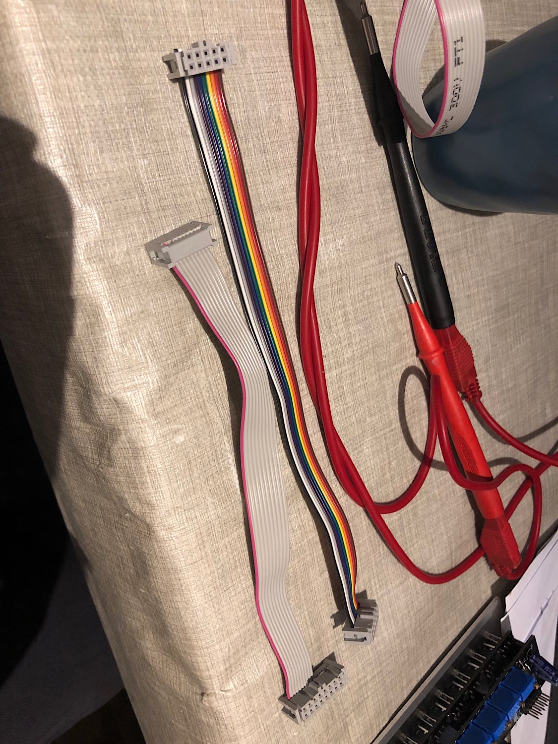
* I am using an official moog eurorack power cable, i have to mention something strange. When looking at Peters tutorial he i making the eurorack power cables like straight cables but when i compare them to an official eurorack psu cable they are all twisted. Difficult to explain but when i try to use the cables like Peter is making them i dont get any power. When i also twist them like a moog eurorack psu cable it is working perfectly. I really 100 times checked the video and i know it is exactly the same but no power. BTW this is only with the eurorack psu power cable but the module interconnect cables are working like how they are made in the video (confirmed by testing the gate/clock panels).
* I think i screwed up with the DACs .. they were so tiny that i resolder them a couple of times. For all the boards i made i am 99% confident that the soldering is good. But with the DAC board i have a 20% good feeling and i think i killed the DACS. When the DACS are killed do i get the default -5v and what if only 1 is failing? Is there a good way to test the DAC board?
For IDC cables, the most important thing is that the red stripe or pin-1 marker is on the same side for both ends of the cable. It doesn’t matter if the cables loop back around using the strain resistance or not, or in other words if the ribbon enters from the top or the bottom of the connector.
Shrouded headers on the bus boards will force the connection orientation though, so if the cables are “twisted” with the red stripe on different sides, the power polarity will be reversed. Maybe your power distribution has non-standard female headers? Pictures would help.
I don’t think it’s related to this though for the A1 module. Red lights on mean the op amps are correctly powered and with the -5V offset.
For the superDAC board, I hope that you didn’t plug in the Eurorack power there? Pictures of the murder scene? Overheating is possible; what soldering temperature did you use? Having no output would be unexpected. I know that sometimes channels just become less linear.
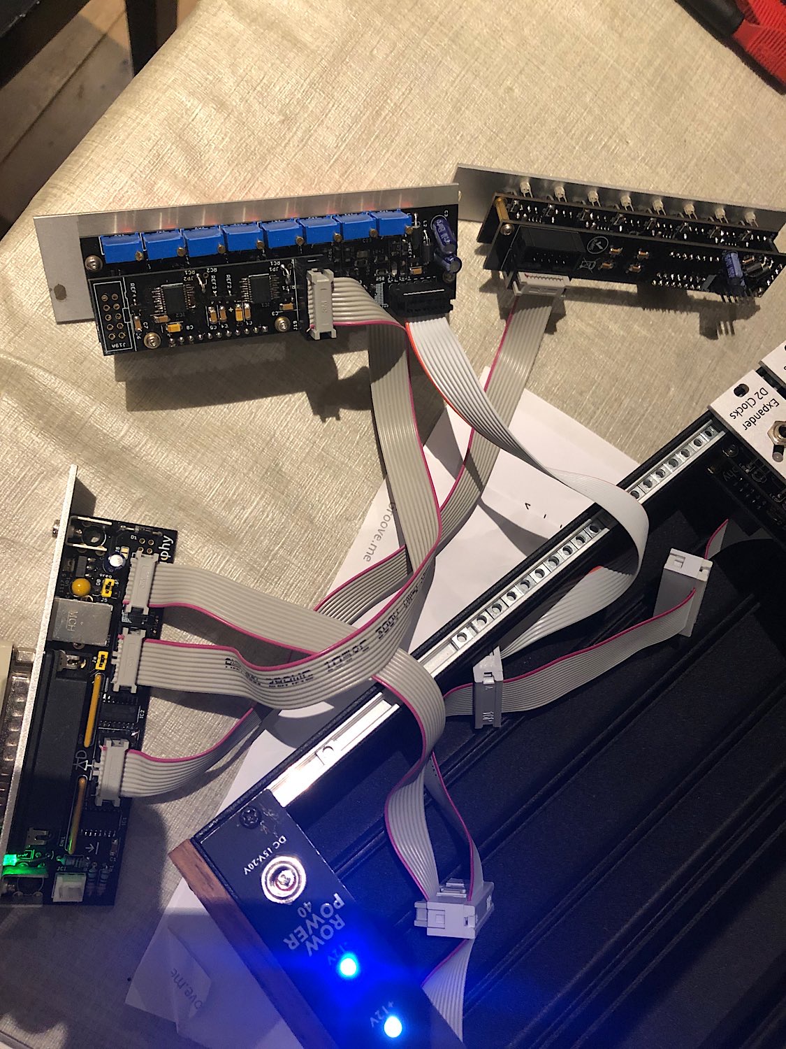
You should have +5V on the red pins, 2.048V on the blue pins. Yellow should be the DAC output. You should be able to measure this voltage or on the 11-pin header.
Use the MIOS terminal command “testaoutpin” and ensure that you can control each of SO SC RC1 (maybe SI but it isn’t used for AOUT). The issue could be further up the line.
Thanks for the feedback, will try to meassure things tonight but here are some pics of me doing some bad soldering on the dacs and pics of the cabling (only Gatesboard does not have euro power at the moment). 2 be continued
You should have +5V on the red pins, 2.048V on the blue pins. Yellow should be the DAC output. You should be able to measure this voltage or on the 11-pin header.
Check the cables as usual.
I can measure the +5v and 2.048v on the pins but don’t know how to do this with the 11 pin header since I don’t have the exact scheme for this pin layout. I tracked the traces to j19a header and can measure both the +5v and I was able to measure the 2.048v.
Quote
Use the MIOS terminal command “testaoutpin” and ensure that you can control each of SO SC RC1 (maybe SI but it isn’t used for AOUT). The issue could be further up the line.
I am not exactly sure when I do example: testaoutpin sc 1 where to measure the pin sc .
Sorry I am a real noob when It comes to troubleshooting these things since I didn’t study electronics :)
For the cables, it is correct if the red stripe always ends up on the left of the notch. But always check the voltage: the red striped side should be -12V.
The 11 pin header (J3) connects the superDAC board to the transmute8 board. The pin outputs are channels 1,2,3,4 0V NC 0V 5,6,7,8 (0V=ground, NC= no connection). Pin 1 is square shaped.
You can “calibrate” all channels to Max and see if you get any output.
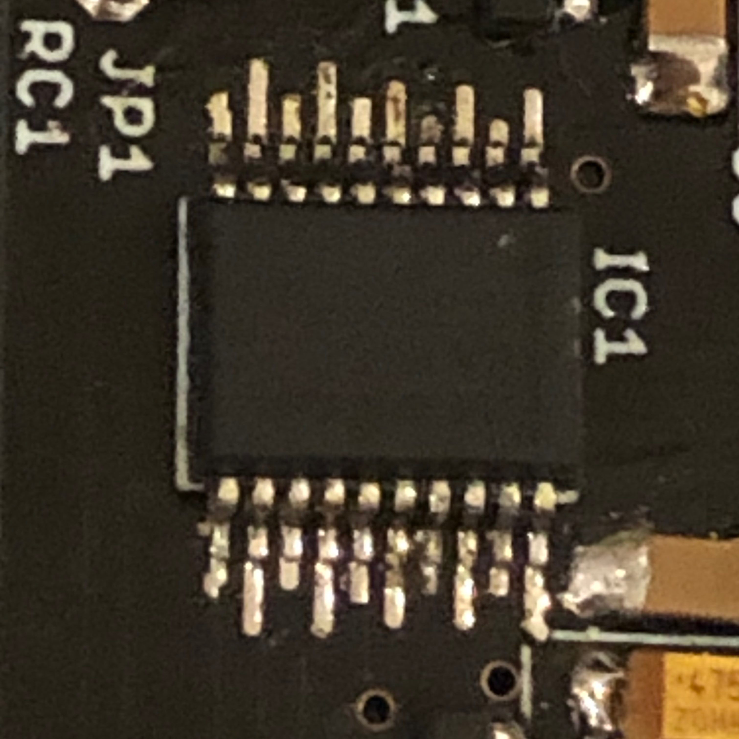
If you’re viewing the board from the top and with the J19 side up and the DACs showing, you have channel one closest to IC1 on the left of J3 and channel 8 on the right side.
For testing the pins, start with J19 on the Euroceiver with the IDC cable unplugged; i.e. measure from the topside of the J19 shrouded header. Once a cable is connected to superDAC, just use empty top pins of J19A. This will work at least for SC and RC1. You could also measure on the DAC pins but be careful not to slip with the probes.
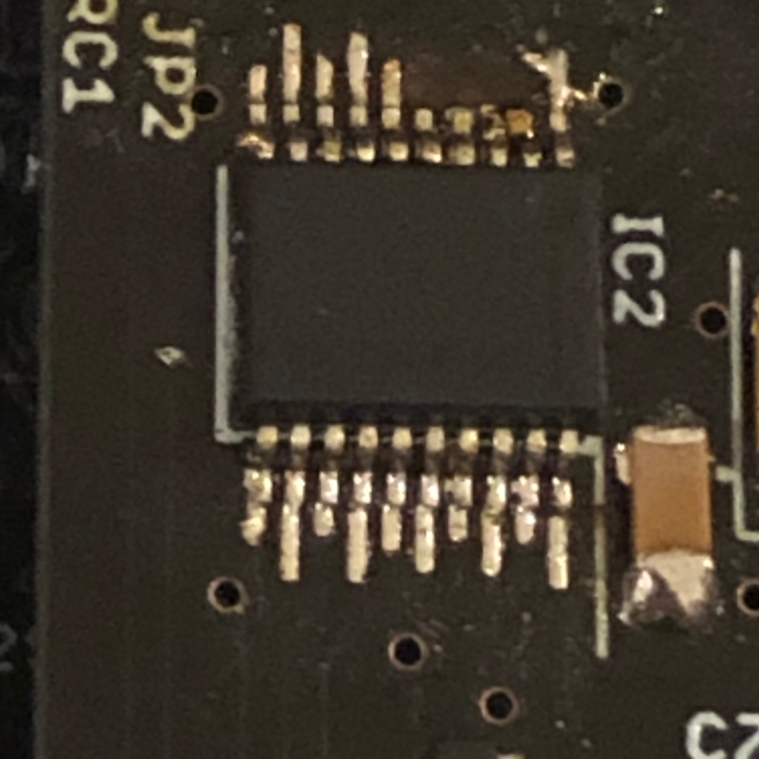
On IC2, pins 2,3,4,5, the pads look quite different, did something happen to them?
Also check that the pads make contact with the IC pins (power off). So test on the pad and the top of the IC pin just to make sure that there is a good connection. Test that no pads are shorted together, except for the channel outputs as indicated earlier.
You can “calibrate” all channels to Max and see if you get any output.
When I measure the pins I only get a value of 0.005v on pins 1234 and 5678
Quote
For testing the pins, start with J19 on the Euroceiver with the IDC cable unplugged; i.e. measure from the topside of the J19 shrouded header. Once a cable is connected to superDAC, just use empty top pins of J19A. This will work at least for SC and RC1. You could also measure on the DAC pins but be careful not to slip with the probes.
On IC2, pins 2,3,4,5, the pads look quite different, did something happen to them?
Also check that the pads make contact with the IC pins (power off). So test on the pad and the top of the IC pin just to make sure that there is a good connection. Test that no pads are shorted together, except for the channel outputs as indicated earlier.
Yes that is the screwup I did with some old desoldering braid and the pads where vanishing like clouds for the sun (Not a pcb issue but a total screwup from my side!) . I can’t find any shorts for now but will reflow the pads one more time tomorrow to see if it helps. Without the J19 connected and CV board only connected by the eurocase power gives all lights red right away. I tested it also with the DAC board disconnected but again all lights red right away (don’t know if this is a valid test :))). Tried different cables for power but all same result.
You’re able to control the SO/SC/RC1 pins on and off? And they make it all the way to the superDAC board?
You can also measure on the DAC SI (Rx) and SO (Tx), pins 9 and 12, respectively. Even better if you have a scope, but the pins should show some voltage depending on the speed of your multimeter. Pin 7 should be at about +5V.
The previous troubleshooting was in another thread, but the -5V state and red LEDs are normal if the DAC channel doesn’t deliver any voltage. In your case it seems like no channels are providing voltage.
Did you try the drag soldering method Peter suggested? Personally I prefer to use a chisel iron tip and just do a few pads at a time, then use desoldering braid to remove the shorts after.
I did some testing and SO is going all the way to the DAC board to the J19A and tested with testaoutpin sc 0 and 1
RC1 is going to the dac board all the way to j19a
SI has a really low voltage on the dac and I hope that I measured it right but I get a 5v on pin 12 SO
I first tried soldering your way since that is my way with chips like the opamps and they are very clean and reliable . With the dacs I got some joined legs and tried to remove it with the soldering braid but that killed 3 or 4 pads and hard to see if they are still there but I get no voltage whatsoever from 16 / 17 / 18 / 19 on the dacs so I think my dacs or pcb is /dev/null . After killing some pads I tried to do some drag soldering with a seagull tip and that worked pretty good but it was to late to clean up the massacre I did.
Maybe ordering a new pcb and some new dacs and things from mouser is the next step.
New update : I desoldered the dacs but the pcb and dacs are too much damaged. It was funny because when I powered it on I some some different colour leds but the psu was making some very slight noise and then they went red again. However it was a sign that the problem is around the dacs I guess. Don’t wanna kill my psu so I shut the thing off and the pcb and dacs are going to /dev/null
Thanks for the update and details. I’m sorry that you had trouble with the soldering but maybe something was learned along the way. On the upside, the PCB can be easily replaced and because it’s modular you don’t have to throw away the rest :).