Hi Sauraen,
I’m compiling my parts list on mouser and just wanted to confirm:
Chip U3 - 74HC137 - 3-to-8 decoder with enable, for selecting board and sound chip
Only one chip and one bypass capacitor is needed in total for a Quad Build right i.e. Genesis Module 1?
Since I’ll be using jumper wire to specify the number of the other 3 Genesis Module boards.
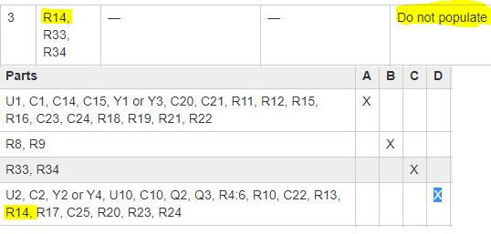
: yes, you found a mistake. R14 is DNP. I updated the page, and also fixed another minor mistake I noticed.
When you’re talking about “enclosure for the Front Panel”, do you mean an aluminum or plastic panel for the front panel PCB to mount under, or do you mean an enclosure for the synth?
: yes, you found a mistake. R14 is DNP. I updated the page, and also fixed another minor mistake I noticed.
When you’re talking about “enclosure for the Front Panel”, do you mean an aluminum or plastic panel for the front panel PCB to mount under, or do you mean an enclosure for the synth?
Sorry for the vagueness! I mean the enclosure for the synth!
Do you by any chance know the model of the project boxes you found? I wonder if they can still be purchased as they’re perfect!
Edit: I see in your original MB FM video that its an electronics training kit. Id almost buy a kit just to use the enclosure!
Would you recommend connecting 2 Voltage Regulators like the OKI-78SR-5 you suggested to it as well as the fuse holder?
I want to keep it simple, so would just like it to run from a 5V power supply only.
Also, I may be getting ahead of myself but where can I download the compiled firmware for MB Quad Genesis?
I checked the MIOS SVN, especially trunk/apps/sytnhesizers, expecting it to be there.
The cases are from Cadet electronics trainers from the late '80s which I dumpster-dived a few years ago. (The more modern ones have plastic cases and are somewhat smaller.) I actually have one case left, but it might not be worth it to ship, as it’s heavy steel. I might recommend you just build something out of wood or whatever.
Any clean 5V power supply should be fine, just be aware that the front panel can theoretically draw up to 1.2 amps (if it turns on all the LEDs at the same time and then crashes so the matrix isn’t being updated). Under normal use it’s much less than that, probably about 300 mA. The supply you mentioned should probably be fine.
The source code is at http://svnmios.midibox.org/listing.php?repname=svn.mios32&path=%2Ftrunk%2Fapps%2Fsynthesizers%2Fmidibox_quad_genesis%2F ; it hasn’t been updated in a while, but when I get home (I’m away right now) I’ll put up the latest version. I never put up the hex file, I was expecting everyone to compile it from source, but I guess that’s dumb and I should put up the hex file too. There’s more features done, including an automatic velocity sensitivity thing–but still saving isn’t finished, oh well.
Thanks a lot man!
Technobreath has volunteered to design a wooden case.
I wonder if its possible to get the dimensions of your own case when you get the time? Maybe the angle of the slope of the wedge shape also.
And if its possible to make them even smaller if theres a lot of space.
Looks like the missing parts of the puzzle are coming together with help of the community!
The aluminum front panel is 15" x 11" (38.1 x 28 cm). The dimensions of the rectangle around the border where the screw holes are is about 36.8 x x 26.4 cm. The case is 10.5" (26.7 cm) from back to front, 10.8 cm tall in the back, and 3.8 cm tall in the front. Everything fits reasonably well inside–there’s some extra space, but especially in the front a lot of that is taken up by the front panel. The height in the back is just right for the stack of Genesis boards.
I didn’t realise that you stacked the genesis modules on top of each other, I like the idea of using headers instead of cabling for the data lines and power lines.
- can you provide dimensions of the PCBs in the back mounted vertical? + how deep the CS PCB is from the back of the CS alu plate - basically the height of the standoffs + PCB - is it standard 1.6mm PCB? I’m fishing for if the PCB sandwitch (within the given dimensions) can be mounted horizontally.
- can you provide dimensions of the PCBs in the back mounted vertical? + how deep the CS PCB is from the back of the CS alu plate - basically the height of the standoffs + PCB - is it standard 1.6mm PCB? I’m fishing for if the PCB sandwitch (within the given dimensions) can be mounted horizontally.
"The spacing between the underside of the front panel and the upper side of the PCB is about 0.27” (7 mm), which is originally defined by the encoders and the 3D printed buttons are made to match this. I used 1/4“ nylon spacers/standoffs from eBay plus a flat washer (4-40 or M3) to achieve this spacing. I used 0.75” 4-40 screws to put together the front panel, in which case the depth of the assembly was 0.75“ with the electrolytic capacitors and pin header / IDC connector sticking out past this. The panel and PCB can be fastened together with 4-40 or M3 screws. "
I didn’t realise that you stacked the genesis modules on top of each other, I like the idea of using headers instead of cabling for the data lines and power lines.
Actually it might be worth adding this information to the Wiki. I can do it if you like, and maybe embed the photo you sent.
What length are the nylon spacers you used to stack the Genesis Modules?
And also the male headers and female sockets for the headers?
I see the 4th Module is using longer spacers but I presume you were just using up what you had to hand.
I use metric all the time except when the parts I’m using are themselves measured in English system (e.g. 1/4" spacer or 0.1" DIP spacing). I try to convert for people. (proceeds to not convert below…)
The Genesis module sandwich should be mountable from the bottom rather than from the back, its width is about the same as its height.
The Genesis modules were designed to be stacked like that–you will need a lot of cables otherwise, and some parts like the mixing circuit will be more of a pain.
The reason the spaces are inconsistent is as follows. The wider spacer is a 0.75" threaded aluminum spacer. The top three boards screw into it from one side, and the bottom board and the case screws in from the other side. I didn’t have screws long enough to go through all four. The other spaces are 2x 1/4" for a total of 1/2". As long as you have about that much clearance between all the boards, the spacing doesn’t matter.
The headers are long pin sockets for Arduino shields, added the info to the wiki. The particular part looks like it’s obsolete on Mouser, but once you see it you should be able to get something similar. They’ll be longer than you need, clip the ends of the pins to fit.
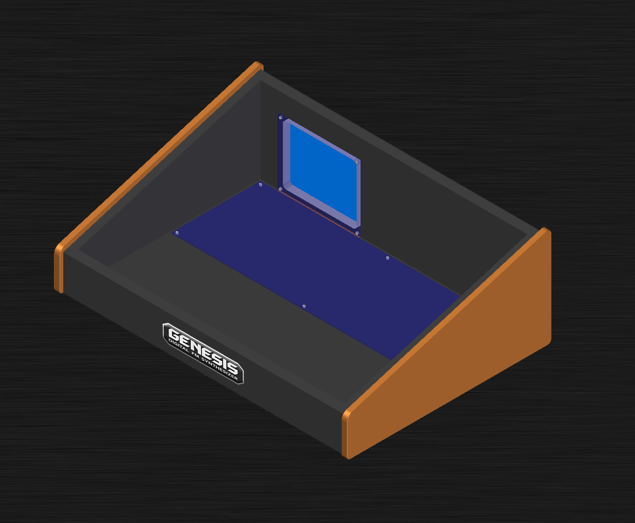
Here’s a draft of the idea me and Smithy has been discussing. An all wooden case. Since it is wood, the idea was to put an alu plate inside where you want to mount the PCBs (wood is more or less alive - I was thinking either MDF or plywood). Those are illustrated with blue panels in there. With this design you can hide all mounting screws (except the ones on the CS panel itself - I can’t do anything about that - and I just praise the powers that Sauraen didn’t do a JB-Weld like experiment with that - because frankly that sucks, and is not robust enough). The only thing I can think of that would make a surface virtually free of screws (like professional system designs mostly look like) would be if you TIG weld alu standoffs to the panel itself in the correct place - and to be totally clear - TIG welding is not for everyone to do correctly, and also it is not for everyone to own or have access to these tools - so better stick to the through hole screws.
If this is something the people think is interesting, I can do a model in exploded view with all parts and dimensions and building tips. Even tho I have had a job in the tech business the last 10 years old - a carpenter is what I’m am in my heart :).
If you guys want this, I can spend some time doing this for you, so there is an alternative to the sorta special case Sauraen uses.
By the way, I have a buddy that owns a large sheetmetal shop, and I talked to him about replicating these cases with sheetmetal. He said, for large quantities, no problem to do it cheap, but for such low quantities, it is not worth the effort. You gotta pay a guy there to make a CAD drawing of it, and then some hours of work in the metal shop. So at least here in Norway, it will not make any sense to offer a custom case made from metal. It is just too expensive. Now, if someone absolutely want that, and are willing to pay, we will fix this too, but it will be a rather foolish thing to waste money on :). Besides - wood is modern nowdays :P.
What do you guys think about this? Something I should invest some hours in? If there is absolutely no interest for it, I see no point in doing it, so give me a hint if you would be interested in building one please :).
And please, I am open for suggestions to the design of it. It is a bit hard to design a case for something I don’t have in my hands, so input is most welcome :).

 lol. Good, good.