The next giant matrix controller with a lot of X ![]()

Created by Ander aka. ALEXander aka. Wackazong
The next giant matrix controller with a lot of X ![]()
Created by Ander aka. ALEXander aka. Wackazong
Lost for words. :drool:
:frantics:
pure madness :w00t:
Jaw-dropping! Congratulations Ander!
Wow!! One vote for MIDIBox of the Summer(/Winter) ![]()
INSANE… :drool: I love it.
Please share your secret of how the switch “cap” works!
You’re pressing a fairly large translucent rectangle. What is it made of? How is it supported?
Maybe something like this would be a great alternative construction for the BLM and other MIDIbox control surfaces.
Hi,
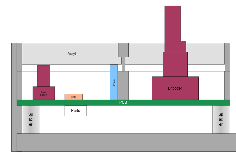
regarding the buttons: Its an acrylic button I had made for me, 6mm of opaque acrylic plastic. It fits directly into the case and is secured by a small notch so it cannot fall out. One side is supported by a small piece of elastic foam, the other side has the pushbutton below it, so that the led can sit in the middle. Quite simplistic, actually, but it works very well so far. Next time I would put notches on both sides and tink MUCH more about the mechanics before building them, but as long as it works now I am happy :).
While I am at it: Many thanks to you for supporting me during this project. I could not have done it without the help of you and the great MBHP. I will try to post some photos, source and docs here in due course.
This is how Spock would compose music on the Starship Enterprise! ![]()
Absolutely beautiful and futuristic looking, i love it.
Thanks Wilba for posting the pictures. BTW, this was all hand-soldered by me… Very meditative.
I have made a quick drawing of the button mechanism. It works quite well, you can push on it everywhere on the surface and it activates the button. I selected a pushbutton with only 150g of force.
what a horny part!!!
Who’s afraid of the big bad SMD parts?
Gorgeous. Bravo!!
*edit
Ok, after watching the video, I quit. I am taking up wood working, anyone that needs an ash tray or cutting board, hit me up.
Thanks Ander for the diagram… it is definitely something I am interested in trying… It might be possible to use Ponoko to laser cut 3mm acrylic and glue two pieces together to make parts with notches.
I hope eventually you will show us what is on the PCB, and how they are all connected.
It looks like you made a multipurpose PCB that can be either a Core32 or some kind of integrated DIN/DOUT/control surface.
This should be MIDIbox of the Year ![]()
WOW, very impressive ![]()
is there a place where we can learn more details about this fantastic box? Is it based on MIOS8/MIOS32, what software is it running, schematics, what PC software are you using it with, what’s the UI concept, what are all these beautiful buttons there for etc? Questions questions questions :drool:
S
Holy $hit, look at all those parts! How many colours can you make ![]()
And what a great idea keeping the same PCB footprint for the encoder and switch boards. I bet that saved a bit of $$$
Fantastic machine you built Alex. Definitaly midibox of the century!!
Do you use it to drive ableton or is it other software?
It looks like you made a multipurpose PCB that can be either a Core32 or some kind of integrated DIN/DOUT/control surface.
Well spotted ![]() Your are right, the PCB is the same for all modules. It can hold either one encoder or two pushbuttons in the same area, or any kind of sensor with analog output. One PCB can hold 16 pushbuttons or 8 encoders/sensors, or any combination. Actually, one module consists of all the necessary PCB stuff for
Your are right, the PCB is the same for all modules. It can hold either one encoder or two pushbuttons in the same area, or any kind of sensor with analog output. One PCB can hold 16 pushbuttons or 8 encoders/sensors, or any combination. Actually, one module consists of all the necessary PCB stuff for
one STM32 core
2 DINs (in a SMD version)
one step down converter (24V to 5V)
three driver chips to drive 16 RGB LEDs (PCA9635). This is a design of my own, I do not use DOUT modules
The core parts are of course not soldered in on every module, but of course this one PCB design made developing and producing the PCB much cheaper. Its actually 4 Layers, 16 RGB LEDs need quite a lot of routing…
Do you use it to drive ableton or is it other software?
Yes, I use Ableton Live for music production.
PCA9635 looks like an interesting chip… certainly a lot easier than doing PWM in firmware.