See also those nice christmas lights ![]()
Pay will add some more infos below
:o :o :o :o :o :o
that’s most impressive (and by my opinion best) midibox I’ve EVER seen! :o
maybe lights should be more discrete… but everything looks f* GREAT! :o
PayC, can we get some additional info? How pots and buttons are mounted?
Is that a plexiglass material laser-cut and a sticker for labels on it?
My brain exploded. Very cool!
Hi there!
First of all: THNX a lot for the credits again! Means a lot to me to tell the truth. ![]()
At last, my Traktor Controller is done! Started appr. August last year and finished in January. The whole project costed about 400 Euros (with some tools), but I sold a big amount of midibox stuff I still had here and didn´t need anymore (some of you will remember) so I came out to a final amount of about 200 Euros spended for this box. And for such a box this is nearly nothing I think. ![]()
My motivation for such a box is that it´s unique in every sight. The controllers are thought for Traktor but as there are pots, encs, faders and more than enough buttons, the controller screams for more apps to control. Moreover the positioning of the controllers is very untypical compared to a “normal” MIDI controller, so every place of each parameter can be remembered easily (much more easy as with a 8 rows of 8 pots controller, I think). And last but not least, within a MB64E you got the BIG advantage to have every controller type you like including pots, faders, encs and buttons. All in one.
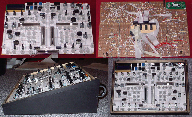
A little stuff, I wanted to implement, too: As compact as possible, desktop case, expandable, backlit buttons (yeah). As for the first point I decided to put as many components as possible onto a breadboard PCB. I misused Eagle for planing this (with the correct autorouter options and a big amount of handwork Eagle is a pretty good breadboard design tool).
So, if we are there already let´s go over to the pics:
Moreover, you can see the fitting of the breadboard in it´s case (there you also see how narrow everything is planned to get a compact box).
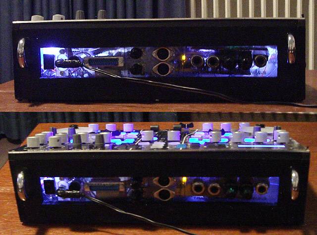
In the case you again see the core (the only thing which was not connected to the breadboard) and on the left a little headphone amplifier (1 audio in and 2 audio outs for two headphones - the headphone level can be controlled much more easily here as it´s analoge). In the middle there´s a D-SUB 25 + cable for further extensions (e.g. making the box Traktor 3 compatible) - there is still place on the core for 32 more pots/faders and 24 more Encs! ![]() And you even can get a glance of the 4 LED´s + reflectors which make the next picture possible.
And you even can get a glance of the 4 LED´s + reflectors which make the next picture possible.
YEAH! 4 ultra-bright LEDs + plexiglass back = cool insight for all those people coming by and asking how it looks like inside. ;D
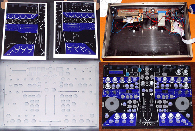
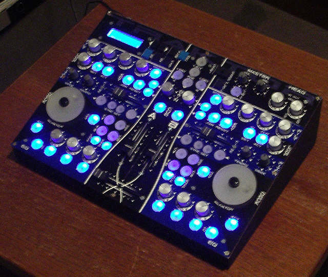
It´s done! Traktor controller! At this place a few more facts:
ONLY (!) ALPS controllers (ALPS pots, ALPS faders and ALPS Encs - only the buttons are not ALPS but self-made for being backlit).
The buttons are made of normal Reichelt Digi buttons + cutted, satiniced and translucent plexiglass. The plexiglass is cut at a drilling machine by miss-using a so called hole-saw (it´s something like a driller, but for bigger holes). In this case the hole-saw does not make holes but nice, perfectly round button tops. Little hole into the middle (appr. 2 mm deep is enough), glue it to the button itself, LED behind it and done is the backlit button.
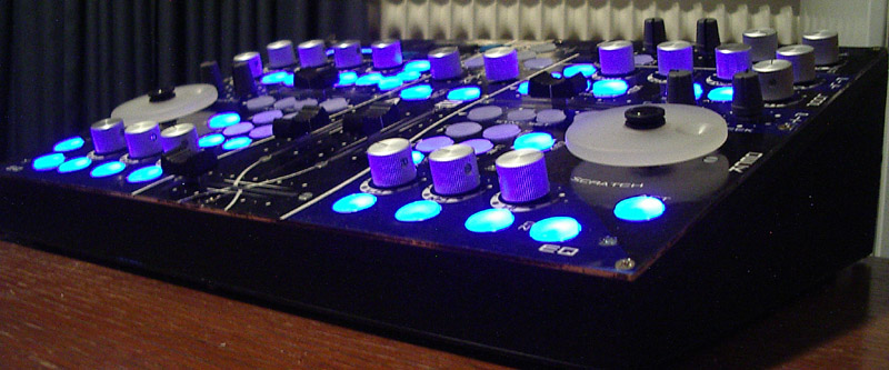
Here you see how bright the whole thing actually is. Even at daylight it´s no problem to see whether a button is switched on or not! Wouldn´t have thought of such a good result. -> me happy ;D And: I love that blue LCD! Really something to recommend to everybody, because for a little more Euros you get much higher viewing angle (for a LCD) and less current (appr. only 75 mA in this case).
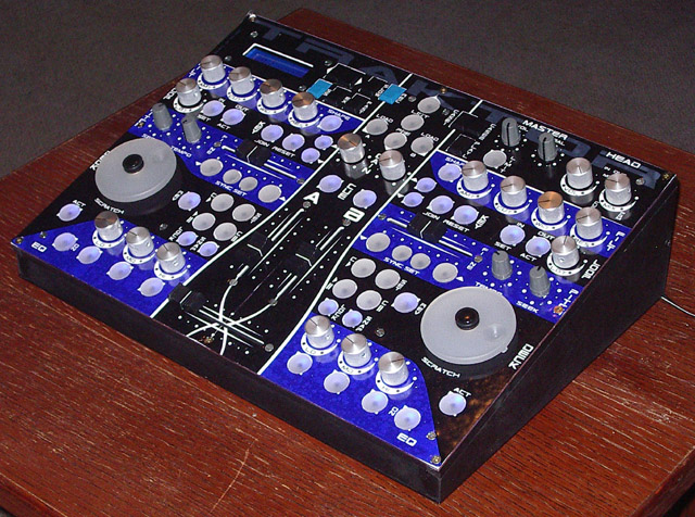
U F O ;D
A cool view of the Traktor controller to bring it all to a cool end. 8)
Gotta go and mix some tunes so: Greetz!
Oooops, all that writing let me forget your question rogic, sorry: Pots and buttons are just soldered to the breadboard, not more. The breadboard itself holds to the frontplate with some additional screws, the encs (screwed) and the faders. That´s it.
The plexiglass in the back is made by myself. I think you can guess I don´t have a laser cutter @home. ;D It´s drilled and sawed and filed in the classic way and then, yes, again some self-adhesive transparent foil, where all the stuff get´s printed in a normal inkjet-printer.
Yeah, you´re right with the LEDs, but in fact (that means in front of me) the backlit buttons are much more mate-like. The light is not so “pointed-out” like you see in the pictures (e.g. there actually is no white dot in the buttons…). ![]()
And still something else: Perhaps there will be some other knobs for the pots. I´m not 100% confident with those now, so I ordered some other ones. Let´s see… ;D
Greetz!
did you make the transparent buttons yourself? Could you give a quick run-down of the process? Thanks.
Congratulations Pay_c!
This is simply one incredible design! It has such a professional looks - it could be an expensive commercial unit. (and it would beat over 90% of competitors in attractiveness!)
Moebius
Moin Pay_c,
erstmal respekt, da hasst du dir ja ein cooles zauberkästchen gebaut, echt geil das ding,
ich habe einige Fragen an dich:
gibt es irgendwo lineare fader mit mittenrastung für den crossfader ?
hab leider bislang keine im Internet gefunden,
was genau kannst du mit den scratch wheels in traktor anstellen ?
muss man ein Display haben ?
dies konnte ich auch durch lesen sehr vieler beiträge bislang nicht ergründen,
deine potis und fader haben 10K oder ?
hier nochein kleiner tip von mir:
ich bin gerade dabei mir das scratch wheel zu entwickeln, dazu habe ich eine defekte festplatte aufgeschraubt und die Scheibe entfernt, hat ca. 10 cm durchmesser , innen 3 cm, absulut rund, und relativ schwer,
mal sehen, ob ich daran einen encoder befestigen kann,
mfg ranger930
Great MBox! I second the question - could you give some details on how you made the illuminated buttons?
Thanks!
-drin
First of all: Sorry for the late answering, I´m actually totally freaking out @work. ![]()
![]()
![]()
Whatever… THNX again and again and again! ![]()
![]()
![]()
For the buttons (I thought I already wrote that somewhere):
The base are normal Digi buttons as those from Reichelt (the classical SID-Buttons) - these cheap ones.
The top is made out of 6mm Plexiglas (translucent and satiniced on both sides type so the light is diffused nicely). I cut the round thing out by mis-using a “Lochsäge” in German - I think holesaw on English could be correct. The holesaw is a tool for cutting out bigger holes with a drilling machine. But if you put the middle driller away (which stabilizes the thing while drilling the big hole) and use it @ a good stand-driller you can use it to drill those round buttons out of nearly everything (DO NOT use it with a hand driller - you will kill your material - not a chance to hold still). Just go through and get the round plug out of the holesaw (most holesaws can be put into parts for that). A little training is needed for the whole procedure but then it´s no prob.
The end is a appr. 2mm deep hole into the middle of the button (that´s a little tricky - you really have to aim for drilling as exact as possible into the middle) with a diameter of 3,5 mm. That´s the point where the base button (that Digi button from before) gets glued to (I used 2-component stuff again) - while the glue is still hardening out you can adjust the top so it´s sitting horizontal on the button. Voila! Just a LED right behind it and that´s it. ;D
@ranger:
I will switch to english if that´s ok for you? DO NOT THE HELL use a middle-detend crossfader! REALLY DO NOT! Not *one* DJ-mixer on the world got that! Just use a good fader (P&G or ALPS) which goes smoothly for that.
The Scratch wheel is activated by the button next to it. If the button is pressed, the record is stopped and you can go forward/backward with the scratch wheel - the feeling for that is a bit hard to get but it works (somehow…) - no good option if you think of scratching that like Vinyls… it´s a *BIT* different… ![]()
You don´t “need” a display, but it´s very useful if you want to change the setup the fast way. In my opinion, a display can catch up a LOT of problems. Without a display you can get into different situations where you don´t know what´s up now. I recommend it for nearly *any* Midibox.
All pots and faders have 10kOhm, right.
Phew, enough for now. GREETZ! ;D
english is not a big problem for me,
ok, i understand the funktion of the display, and now i think it’s better to have,
@ to all:
i want to have a control led that shows me the middle postion of the crossfader , has anybody an idea how to realize that ?
i want to use a small fader from alps , 60mm
thank you all, ranger930
what exactly midibox is PayC’s MB64E?
I see on ucapps.de that it has only support for encoders & buttons ??? what about pots ???
what exactly midibox is PayC’s MB64E?
I see on ucapps.de that it has only support for encoders & buttons ??? what about pots ???
check out the changelog:
http://ucapps.de/midibox64e_changelog.html
-since 2.1: “experimental” support for ain and mf modules
@ranger:
Perhaps use a dual-comparator IC + a logic XOR device and connect it to the slider of the fader? The first comparator channel is set to 2,4 volts, the second to 2,6 volts. Both outs are going into the XOR: The output is then on high if the voltage is between 2,4 and 2,6 volts. But for that you should perhaps open up another thread.
MB64E supports ALL!!! ;D ;D ;D 8) (even motorpots if no multiplexer is needed)
Those buttons are SWEET!
Might it be possible to wire the SID ModMatrix with buttons like these, so you can in fact press the LED in the matrix you want to light? Now THAT would be cool…!
Thumbs up for your box pay_c! Admirable work, as always ![]()
First: THNX! Like always happy about such comments! ;D
Nope, not with those standard buttons. What is possible to use buttons which have two seperate channels and wire them up correctly. With one channel buttons you would need one DIN for each button and that´s easily to much. If you find some two-channel-buttons in the right size somewhere tell me! That´s easy to wire up (one channel for the left side of the matrix, one for the upper channel without any hardware or software changes needed).
Greetz!
Can’t you just wire the button to left and upper channel on the same pin? (You see, I’m not hindred by any knowlegde about this stuff ;D )
Just think a step forward:
With a 2x2 matrix only as an example (it´s the same within bigger matrices)
That would mean that x1 and y1 (outputs) is connected to the pin of Switch11 (x=1, y=1) = Sw11
But also the Sw21 is connected to y1 and Sw12 is connected to x1
So if you press Sw11, Sw21 and Sw12 will be grounded, too
As the Sw22 is connected to Sw21 and Sw12 over x2 or y2 it´s grounded, too
the wohle matrix is grounded if one switch is pressed ![]()
So within the SID hardware you would need a two channel button. With other hardware´s matrices with one channel buttons are possible (think about connecting x and y without any grounding involved), but not here.
Greetz!
So, why can’t we connect X and Y, instead of both with ground? Is that software related?
Still, I don’t see (n00b as I am) what the difference would be between shorting X1 with ground and Y1 with ground at the same time, by pressing either one or two buttons… please explain it to me, I must look so ignorant :-[
Yepp, you would need another software for that. The hardware (I think) would have to be redesigned, too, but I´m not sure about that.
If you only use a button with one channel within this matrix, you will automatically draw all buttons to ground, because all buttons are interconnected (if this is not clear, try drawing the schematic quickly in front of you - then it´s clear). With a two channel button this will not happen (again: Just draw the schematic for that).