Awesome! Great project!
One thing that came to my mind when I saw the video:
The main label on the displays is good to read… but the small labels on the sides seem to be very small… can you even read it? 
Awesome! Great project!
One thing that came to my mind when I saw the video:
The main label on the displays is good to read… but the small labels on the sides seem to be very small… can you even read it?
Thanks, FantomXR!
Yes, the displays are very “sharp” and can be read without problems from 40-50 centimeters. Unfortunately, the cam sensor captures a bit of flicker, in reality, they are really great - just like a high-res computer screen :-).
Regarding the “positional memory” of your hands: the main labels are intentionally used as “pathfinders” to find the region of interest (e.g. filter), then your hands remember which of the four encoders to grab after a while - it works quite good so far - we will have to wait and see how it works on a bigger synth with multiple pages/banks
Many greets,
Peter
J: no worries with the soldering! Regarding the 3V3 supply, a standard LM317 works very well here - it fits on 2x2cm vector board. A switcher with an additional 3.3v output is not mandatory, but of course you can use it! For 5V, i used a LM2596 switcher, that i had leftover, just as you recommended! It works great, you can feed it with any input voltage up to 30v and it is efficient.
There’s a few different ways to get this show on the road. I’m looking at some compact MeanWell, with a 5V output. Then, making a separate 3.3V for the OLEDs, buffered with some uF- sized caps so that any OLED-related ripple won’t spread to any critical voltage supply. /J
I plan to build a DAW Controller for a while now and I wonder if this still can be supplied via USB (if I don’t use Motorfaders of course). But I think 9 - 10 Displays shouldn’t be a problem if I use the 5V and a regulator instead the 3V3 of the STM, right?
Here is a rendering:
<___base_url___>/gallery/image/2536-daw-controller/?do=embed
… looks good!
I dunno how much current your other elements draw, but for the Programma, adding the 7th display gave some strange problems that could only be solved by *both* adding a 3V3 vreg and obtaining the 5V not via USB.
That was probably caused by overload by the many LEDs, drawing quite some current and the STM32F4 regulator, that seems to be a 3V0 (?!) regulator - i measured 2.9V input voltage to the displays, which is already a bit low for the internal charge pumps.
As you probably don’t have soo many LEDs, it could just work fine. But as you probably need power for the motorfaders anyways, adding a LM2596 (or similar) to obtain 5V seems recommendable.
Many greets,
Peter
I like the style so far, good job!
LT1963 is a good low dropout Vreg (340 mV) at 1.5 A max current. You can get it in 3.3 V fixed version; a variable one supplies voltage to most TTSH VCOs. So if you had a 5 V SPSU at a couple of amps, this could supply the juice for the displays.
Thanks! Regarding TK.'s wish for more buttons on the control surface…
How about using the menu button to enter a “fullscreen labelled menu” mode?
After pushing it, a new page is loaded, that offers up to 64 slots for
* unique actions to be fired (e.g. .ngr scripts)
* configuration settings to be modified
* synth patches to be loaded from sdcard and dumped to the synth
* synth patches to be stored on sdcard
* programma configurations (aka which synth is controlled) to be loaded
via a single tick/turn of the respective encoder.
The OLED labels would show which action is mapped to which encoder.
The encoder LEDs can be used as function status LEDs, when necessary.
Also, on this screen, certain settings could be adjusted, like the MIDI output channel for the synth and so on.
Would that work for you? It would be like a giant flat menu system available (without hierarchy/scrolling) after a single button push, with many free slots for user actions (e.g. ngr script launch).
Many greets,
Peter
What about encoders with switches? The LRE8x2 boards support them and you go enter a mode which disables the encoders so you don’t accidentally turn them and change a setting.
Hawkeye and I are only using encoders with switches. Makes preset selection fast and painless if we so choose :yes:
I like the LT1963! I was going to take a little peek at my project notes, plus visit with some local DIY gurus before I commit to any PSU design. I could write lots, but I don’t want to expose the reader to a snow job so some research is in order.
Do the LEDs really draw so much current? If you’d connect them directly I would understand it. But at the LRE the LEDs are in a matrix… it would be great if someone could somehow measure it… would be interesting to know anyways.
For my DAW controller it was planned, to support USB-power (without motorfaders of course). It has 9 Displays + 9 LED-bars right next to the faders. So, if the STM-Core is not able to provide the needed current / voltage, I thought I could add a 3V3 vreg directly to the USB-jack, which has 5V. The question is, if the whole thing (STM + extra vreg) draws more than 500mA, which is the spec of a standard USB-port on a computer…
The LEDs are multiplexed, you might have more of a problem with motorfaders.
I hate cable clutter as much as the next guy, but I would add a cheap and cheerful MeanWell switcher to a DAW controller just to be on the safe side. That way you get to connect to 115/230V directly using a normal 3-prong C14 inlet. I’d rather do that than having to use another wall wart.
Regarding the current draw of the LRE-boards - i didn’t measure yet, but - we are talking about 32 shift registers, quite some ULN darlington transistor arrays and 4 x 16 LEDs that are lit at once (multiplexed). So for the LEDs alone, that could be 64x ~10mA of consumption -> the LEDs alone are far above USB power specs.
That causes the 5V rail to drop, and then weird things can happen. -> J’s advice of using an integrated switcher is a good one. I went for the cheapo wallwart + LM2596 method, cause both were floating around anyways 
Many greets,
Peter
Puh! Be carefull with advices to work with 115V/230V directly. In my opinion it would be better to use a powerful wallwart like Hawkeye suggested… I know that a wall wart is not perfect… but in the end nothing will happen to you with 5V. It looks different on 115V/230V.
//edit: @ Hawkeye: So you use the LM2596 for STM and the other stuff together?
//edit: @ Hawkeye: So you use the LM2596 for STM and the other stuff together?
Yes, it is a nice LM2596-based 5V-5A switcher, that i use with confidence in flying projects as well:
http://rctimer.com/product-160.html
it is cheap and also already comes with a connector, that fits perfectly on the STM32F4 core board - just pull the “USB Power” jumper, add this thing, and you are out of power-worries You can use an old notebook PSU from ebay (1€) to power it - these often deliver 15V to 19V and are perfect for this job… it can also easily handle the additional load of the linear ldo regulator for the displays…
But, I really like J’s more professional solution of an integrated switching “full” psu - this avoids external cable/psu mess - but of course you must take care to not get electrocuted
Many greets,
Peter
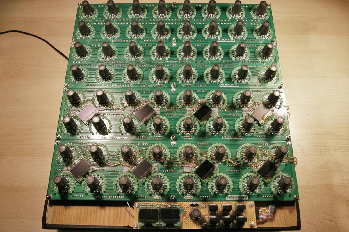
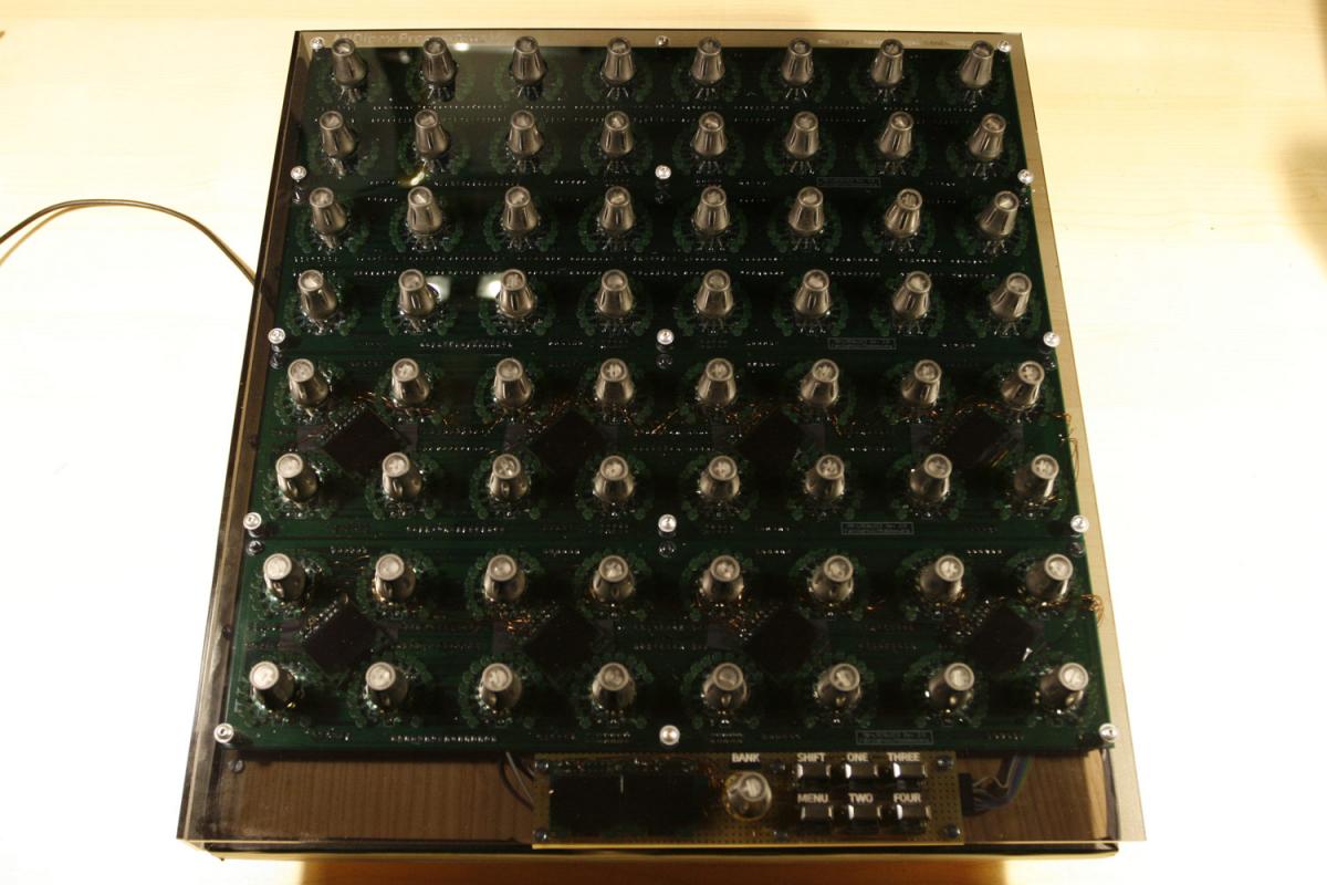
Attaching a few more photos, while we wait for the boat from china to bring more displays
The display cabling is a bit of spaghetti, but well doable with enamelled copper wire. The displays will happily “stick” between the LEDs, they are exactly the right size. Of course, maybe in the future, somebody designs PCBs that allow for easier mounting without those wires!
The encoders currently use a single switch line, that is shared with the “SHIFT” menu button. This could be changed, but then we wanted to save on DIN ports, as the idea was to attach as many LRE boards as possible :). Parameter input accelleration (when pushing the respective encoder) works fine and is really intuitive.
Many greets,
Peter
hopefully the whole hardware thing and synth remote…get something rolling called -preset morph-…
Planed Feature: “Morph” function to fade smoothly between two snapshots"
i love soundmorph, i could jam the whole day arround, and then i make a snapshot/save Preset,
on gigs the croud dont give me the time to jam the whole day…
>>>some crossfade between sounds is “doing less sounding much killer feature”
with the possibity to exclude some CCs from that morph - like:
LPF-Cutoff, Fiter-Env.Ammount, >>> - for all the filterheadz out there who still got to have controll over the sound while morphing.
>exclude the morph Controller from morph fade, morph the morph may end in endless cc traffic sessions…
Select the “to be morphed CCs” by hold a “shift”(morph)-Button, now all LEDRINGs are blank by turning a Encoder the dedicatet Ledring lit up > that indicate that this CCs will be morphed…
Next to the MORPH-Button is the Morph encoder, and next to the Morph Encoder is one of this Dispays, that shows on the left the actual Preset, and on the Right the GOAL/Destionation Preset. 2Encoder and one Button should do the job…
I think it’s not released yet but I have a beta-version, which is not tested at my side yet.
Check that out:
http://discourse.midibox.org/t/topic/18780
It’s not exactly what you wanted, but it’s a great feature anyway!
i cant test it, i dont have controllsurfaces with ledrings on it.
looks like the “morph assign” feature that the nordlead/rack III has - the NordRack III has a LEDRING Interface:
When you press & hold one of the Morph Assign Knobs (Velocity, Keyboard, A.Touch, Wheel) all Ledrings are turned off , and then by turning one or more Encoders you assign it to the pressed Morph Source (e.g. a CC).
The Ledrings inital Position is “middle” if you turn it left, the Morph Source is substractetd , turn right and you add a Amount of Morph… in the Nord Rack Case you have then -64 +64 of Maximal Morph Impact (not 127)
Since the Nordrack has “Dual-Colour” Ledrings, this ammount of Morph is indicatet by a differnt colour (Grenn is the morph Factor, red is the CC amount before the morph additon) this could be simulated on the MB-Side with a blinking LED, or with a “show morph” button.
that meens techically:
the morph CC is addet by the ammount off the morph factor
the morph Factor is set Holding the Morph-Assign-Knob + by turning the Destination CC, the result is a int from ±64, for example we turn “+32”
now release the Morph-Assign-Knob - now we are in the normal “Perform-Mode”
I now turn the Destination-CC to 64. (=Ledring-Value)
when i now turn the Morph-CC, to 127, the Resulting Destination-CC-Value will be 96.
a cool feature, but only when you see what it does by indicating it wih differnt colours, or some blinking…otherwise it is confuzing…
Yes, I think, the morph function will be great!
When MBNG supports it (it is still on the wishlist, i think), the Programma, which is nothing but a MBNG, will do it, too!
Many greets,
Peter
NORD does in generally work exactly like this and they have just single color LEDs. I don’t think it’s confusing. I worked with this for many years on many stages. Never hard problems