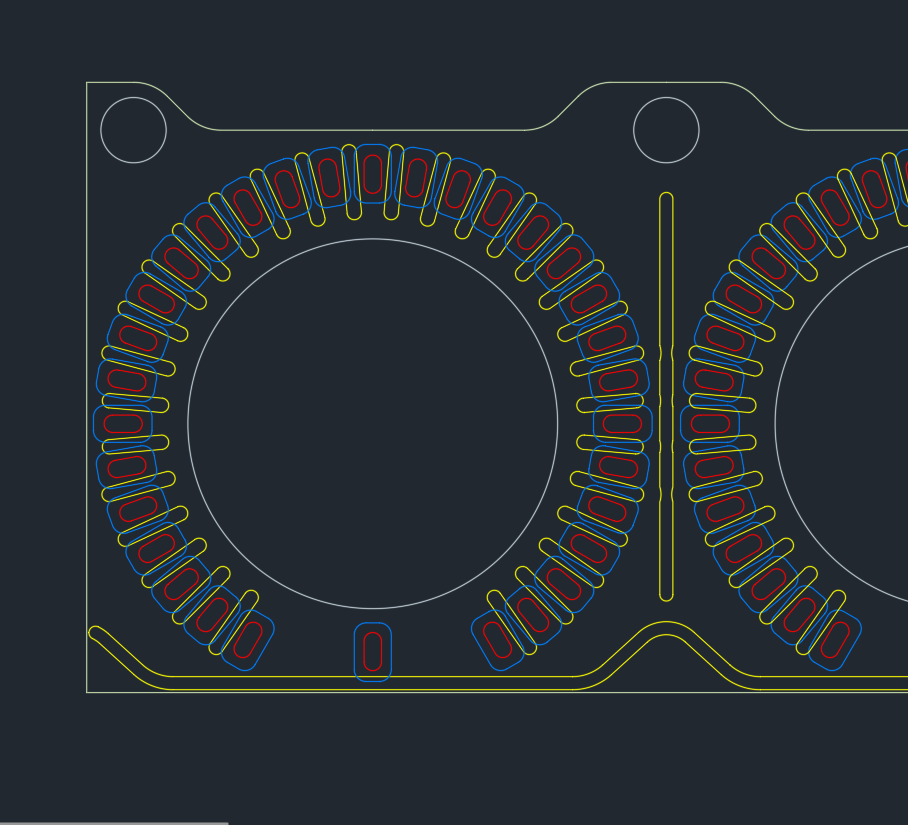
man that finished frontplate looks so incredibly amazing, insane job, congratulations again. what kind of router & bit did you use to mill the PMMA? not sure the CNC at my fablab is fine enough.. not only are my measurements a good bit smaller but also i start realizing the laser cutter with its convexed cutting edge is not really precise enough for light channels like that.. so the biggest issues of translating your approach would be the holes in the black MASK layer, or rather the walls between the holes. i did some quick maffs, if we go 36>32 that will give me an additional width of the radial gap between each of the LEDs of 0.2-0.3mm, at the smallest most inwards point. so almost double what it is right now, i would have around 0.5mm at the smallest point which should make the masking much easier. might still have to CNC and not laser cut. oh and trotec FTW, they were the easiest and nicest to deal with too. innograv almost didn’t take my business lol.
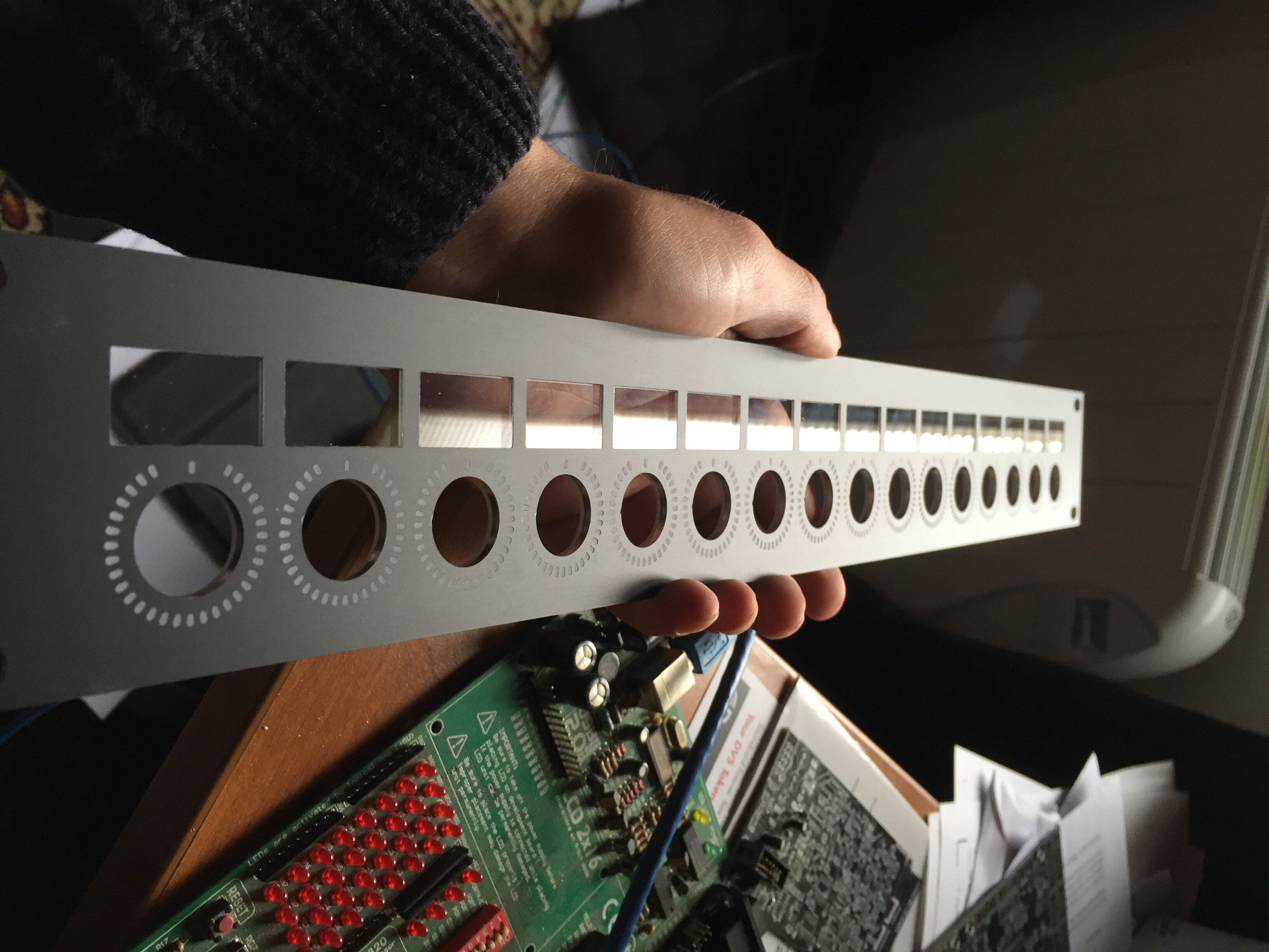
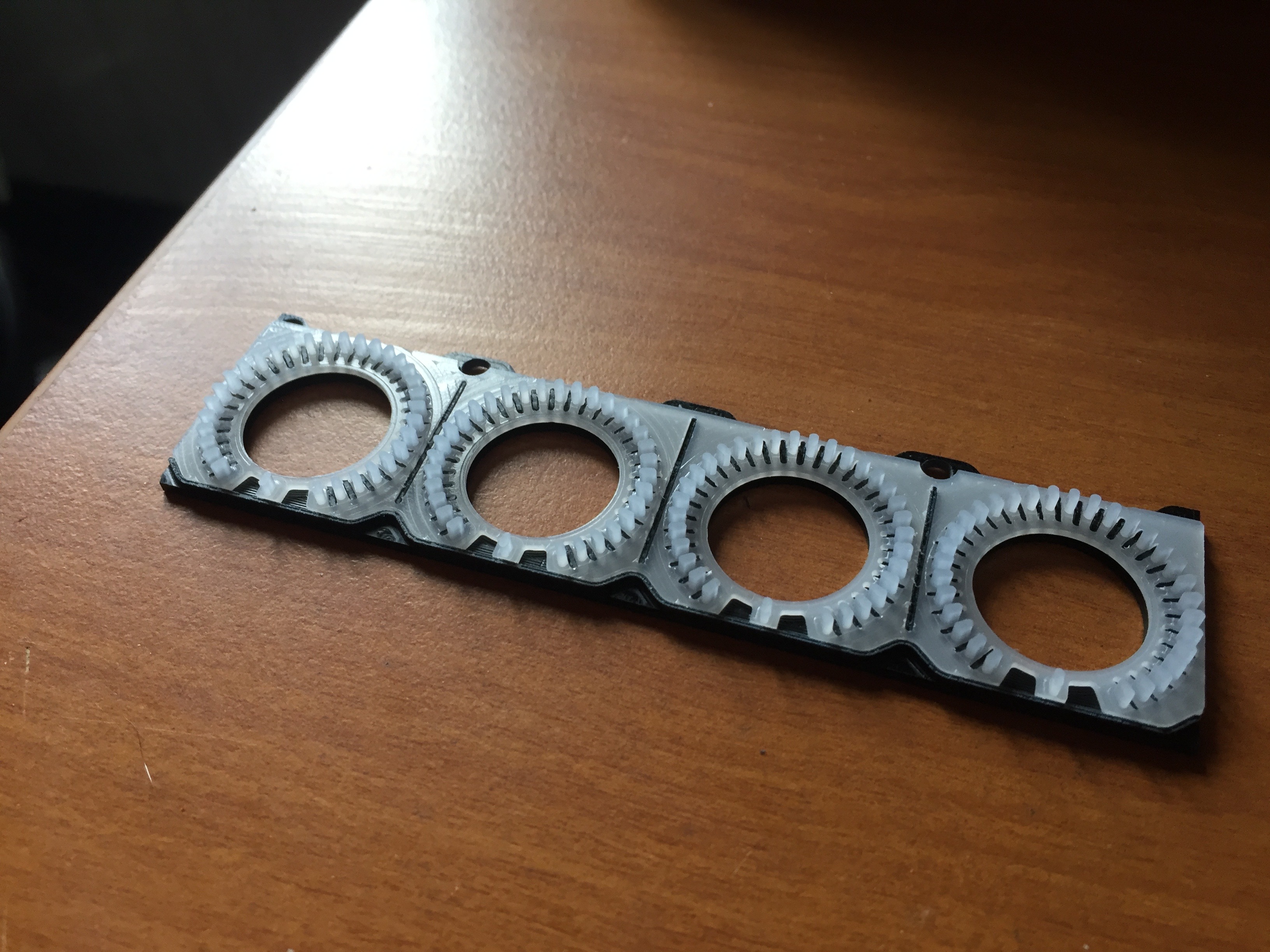
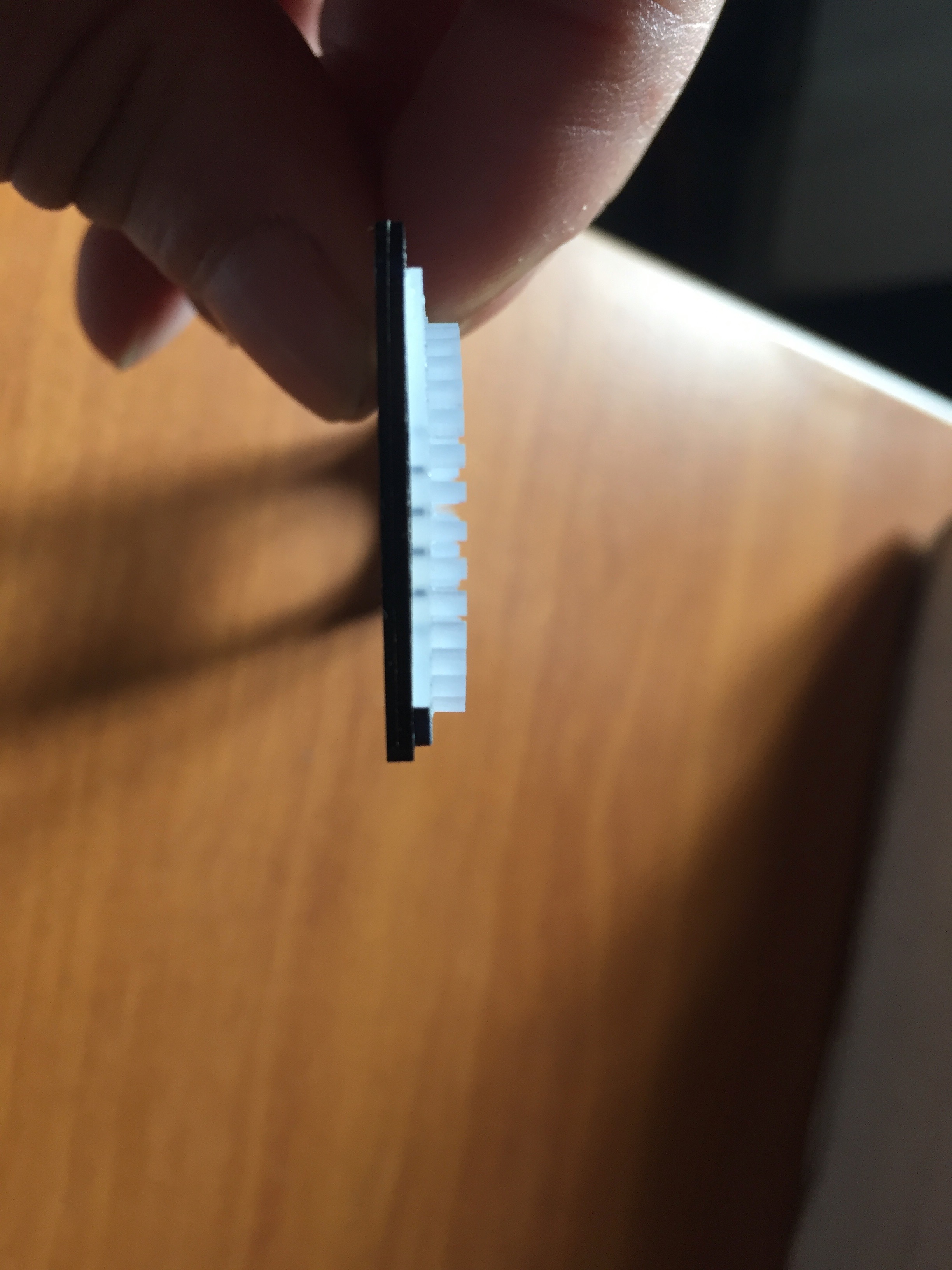
oh bruno if there is any chance you have some pictures of the MASK and WINDOW layer combined with the LEDs stuck through? or any more close up/side shots of the all-layer frontplate. that would be formidable oui oui.
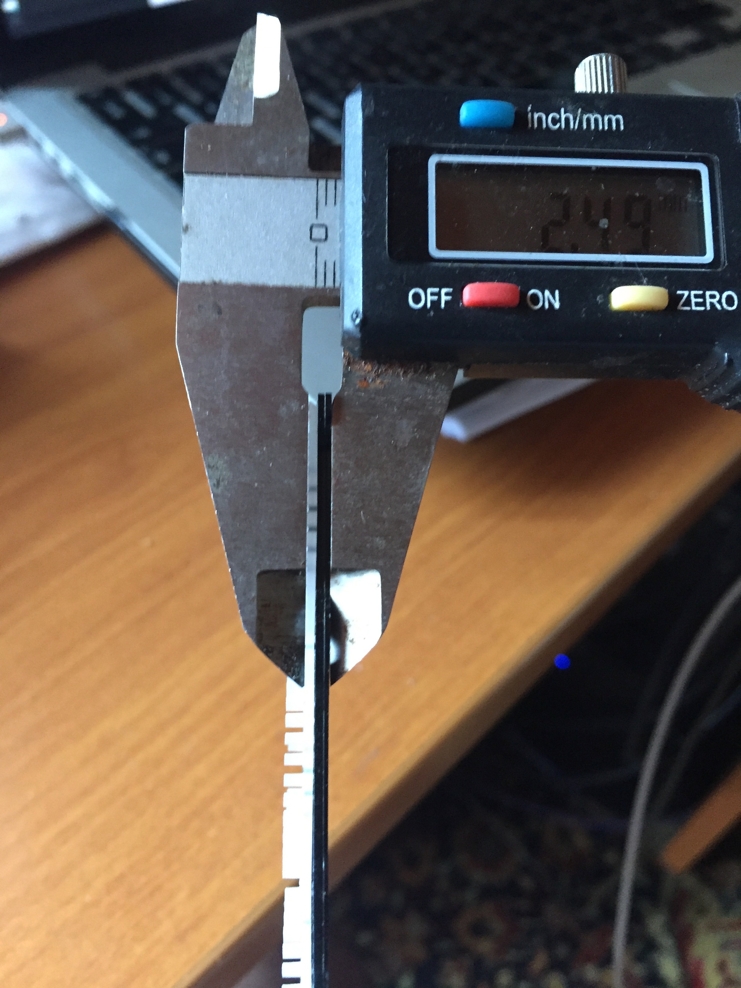
i ordered a bunch of different epoxy/milliput/sealer combinations too though and still wanna try just casting/filling the whole 0.84mm height around each LED. anybbody ever tried filling frontplate LED holes with epoxy or similar?
EDIT: epiphany? what if i make a silicone negative of the fully assembled LED ring board, and then cast a theoretically perfect resin/epoxy mask from it? where do i learn about this haha. oh wait. i need a double negative casting shape. prolly all too much effort, i wanna make music not get into plastic manufacturing.
also i will try some ready made light pipes - anyboby has a good source for those? mouser etc start at 50ct/piece for the 1mm ones, that would be 70EUR per 4x1 board lol. have some regular 1mm and 1.5mm optical fibre cable coming too but i assume that will be hard to cut to size precisely and make it perfectly flush with the frontplate?
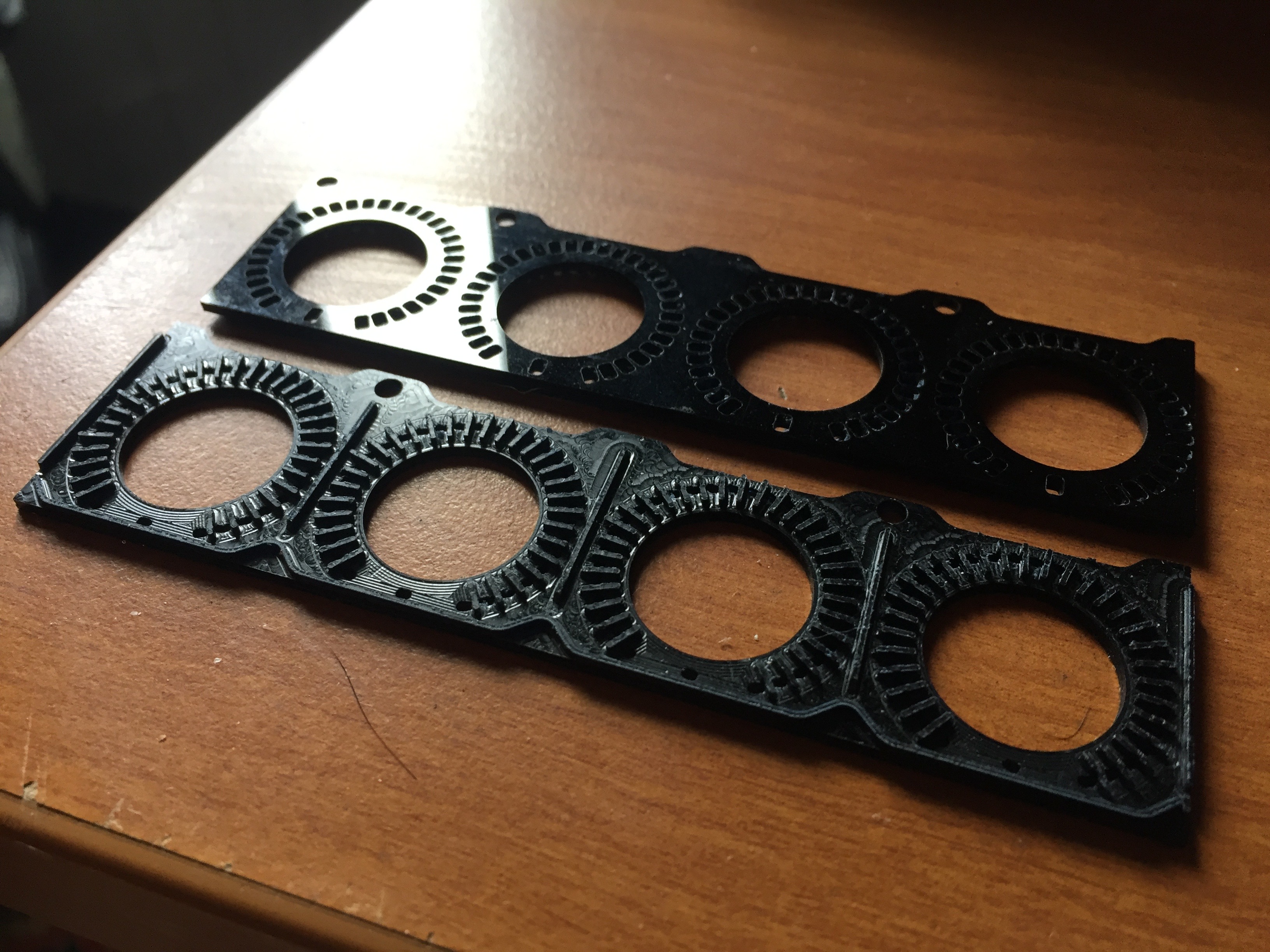
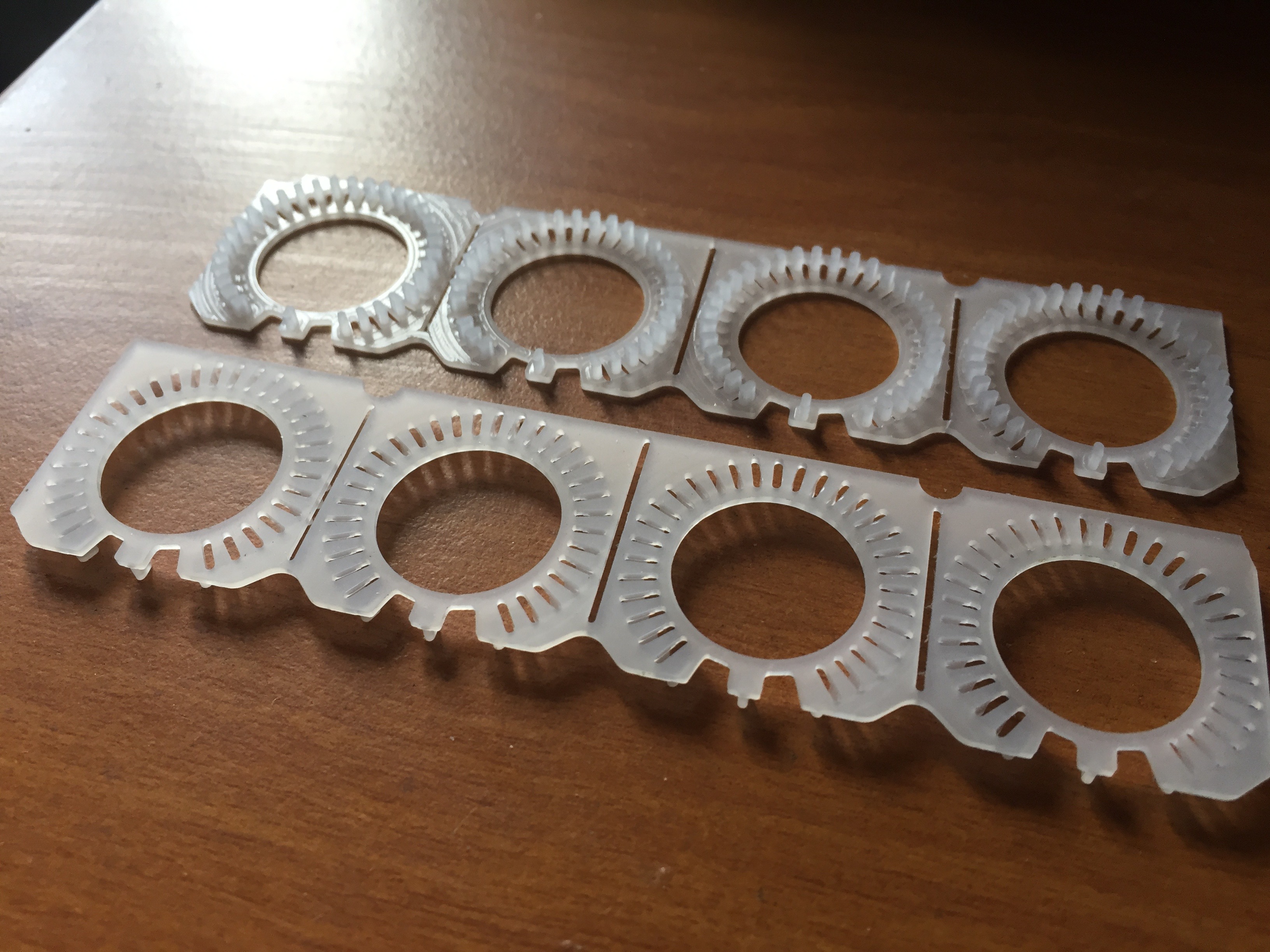
made some more lasercut cardboard masks last night, i think they came out better but probably not perfect. will test and report tonight.
thanks, yeah i somehow was sure you would consider expanding the code after we approached this barrier… i know you’d do that “im schlaf” basically. but here’s my opinion: other than RGB LED rings probably nobody would ever want to connect that amount of WS2812 to a midibox. i personally would LOVE to be able to avoid the extra arduino, i just went there lacking an easier alternative, i didn’t prefer it at all! so of course, midibox support would be great, but if i understood it correctly you want to reduce the amount of work you personally put in on midibox, and given that, i am also not sure if it is worth your time to work on this this driver. maybe you should save your much appreciated midibox time for someones more urgent problems? would love to hear other people’s opinion on this. cause on the other hand the WS2812 is such a stable in the DIY world by now.
i’d very happily send you whatever display/mapping/ring-style code i have if you end up doing something. for you to laugh at, delete and redo properly.
EDIT 2 i can’t stop staring at your frontplate bruno haha so beautiful you need to sit your ass down and finish these.