11 hours ago, FantomXR said:
not sure, what do you mean. Could you explain please?
It needs something like:
- 7 NAND gate - 2x 74HC00
- 3 D-type FF with Set and Reset - 2x 74HC74
Clock inhibit is not necessary.
11 hours ago, FantomXR said:
not sure, what do you mean. Could you explain please?
It needs something like:
Clock inhibit is not necessary.
On 8.5.2019 at 3:25 PM, weasel said:
it is 105 CPU cycles which at 168 MHz amount to 1.25uS.
This calculation is not clear to me.
1 CPU cycle @ 168MHz is about 0,006uS
105 x 0,006 = 0,63uS
Or not?
Quote
This calculation is not clear to me.
1 CPU cycle @ 168MHz is about 0,006uS
105 x 0,006 = 0,63uS
yeah so at first i just randomly tried multiplying the result by two and then it was right and i thought “well that’s one of these programming things where you just hack a ‘+1’ and then it works” and never find out why.
but then i found this line
// timers clocked at CPU/2 clock, WS2812 protocol requires 800 kHz (1.25 uS period)
CPU /2 clock
so it actually adds up. or rather divides up.
10 hours ago, weasel said:
yeah so at first i just randomly tried multiplying the result by two and then it was right and i thought “well that’s one of these programming things where you just hack a ‘+1’ and then it works” and never find out why.
but then i found this line
// timers clocked at CPU/2 clock, WS2812 protocol requires 800 kHz (1.25 uS period)
CPU /2 clock
so it actually adds up. or rather divides up.
There’s some prescaler in the RCC registers(Reset and Clock Control) for all peripherals Clock Source. Those registers are also set in mios32_sys.
For the Timers clock this Prescaler is 2, means Fcpu divided by 2.
Then you have to take it in account in your calculation… TIMER_PERIOD = (MIOS32_SYS_CPU_FREQUENCY/2) / TIMER_FREQ
Datasheet is your friend for that ![]()
So, I made some progress today.
I’ve tested it on another core (which I designed myself) and there the LEDs were running with the stock-firmware. No changes were needed. So I pick&placed 3 1/3 boards today.
What I still don’t get why it doesn’t work on a core with a discovery-board. Both ran the same firmware…
But I ran into another problem. In my first test I set WS2812_NUM_LEDS to 140. I compiled the firmware and flashed it. It was running fine except that LED 139 and 140 were flickering. Not sure if this is a sign of RAM-overload or if it was power-related. well… I don’t think it’s power-related though because they were also flickering if only they were turned on and all other LEDs off.
Next I tried to set WS2812_NUM_LEDS to 300. I compiled and flashed the firmware. Result: The core doesn’t boot anymore. Since my own core doesn’t have a user-button I have to reflash the bootloader through SWD. I don’t have time the next days to try it. But I wanted to give you an update on this.
And here is a short video of my p&p-machine… it wass running slow because it was a first test.
https://www.dropbox.com/s/89zfhdda1sc2f45/VID_20190510_151248.mp4?dl=0
By the way: I left out the filter-caps because I normally don’t work with 0603 parts and though don’t have them in my workshop and don’t have them in my machine. Should be okay for the prototypes.
Hey people,
we could need some help on this project.
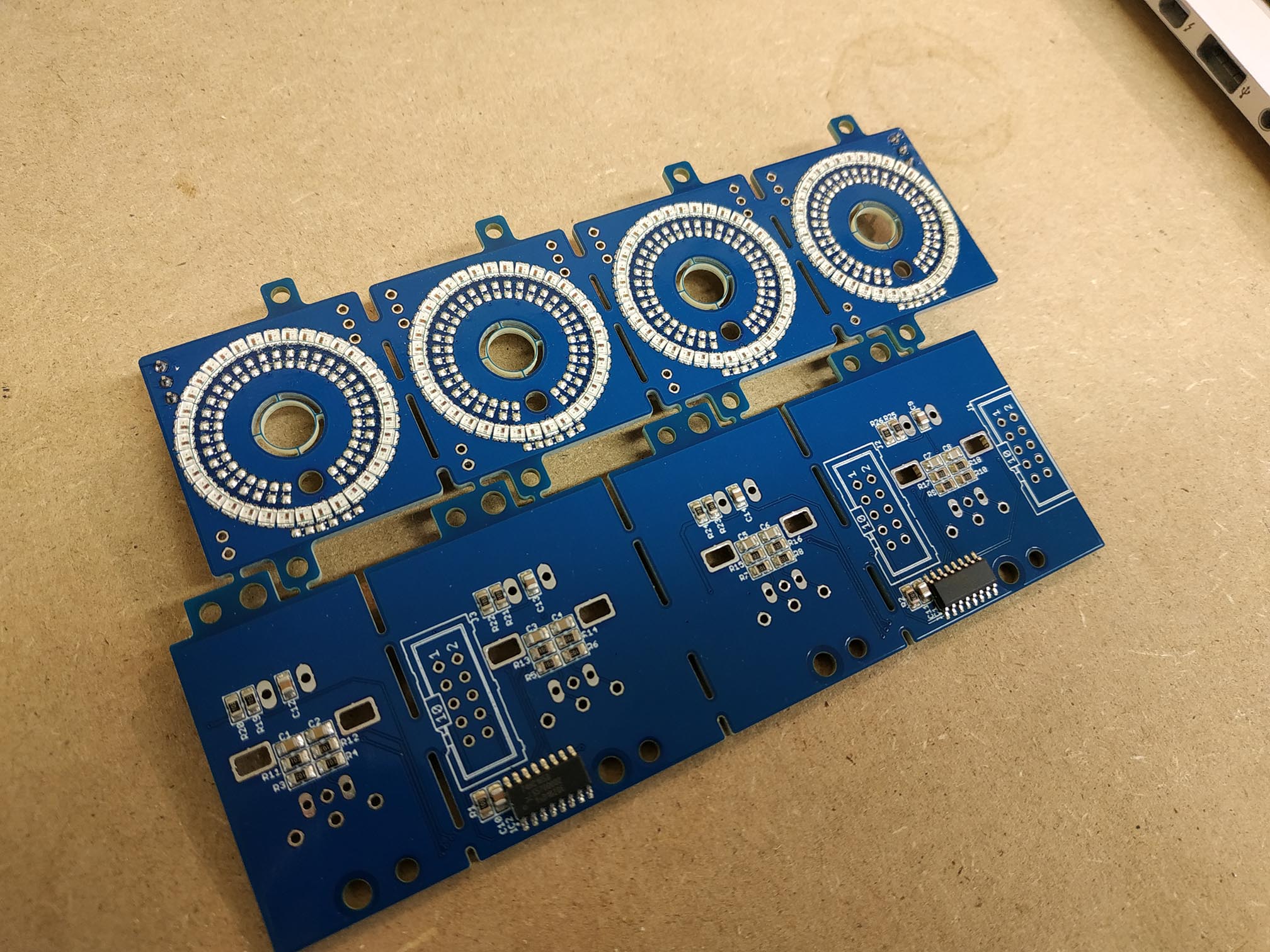
So far the pick and place machine did a great job and the reflow oven as well. So I now have a few boards to test.
But I already run into a problem. In the firmware I set WS2812_NUM_LEDS to 144, because one prototype board is made from 4x36 LEDs => 144. Compiled and flashed. The core boots up nicely.
As stated in my previous post, the last 5 or 6 LEDs are slightly flickering. I’ve tested inserting 5V at the end of the LEDs again but this doesn’t change anything. So it doesn’t seem to be a power-related problem.
Things start to get crazy if I connect another LED-ring-board in series with the first. I set WS2812_NUM_LEDS to 180 (with 190 the core doesn’t boot anymore), compiled and flashed. I think a video can describe better what happens here:
https://www.dropbox.com/s/b5phnsji4k9wjhs/YI051501.mp4?dl=0
Does anyone know where this could come from?! Also does someone has an idea why the cores do not boot anymore as soon as I set WS2812_NUM_LEDS to 190 and more?
Any help would be very appreciated.
Thanks,
Chris
Hi,
STM32F4 was running out of memory - and due to an wrong linker file entry you haven’t got an error after the 128k boundary of the “normal RAM” has been touched.
However, this chip has some additional 64k as a so called “core coupled memory”, which is located at 0x10000000
I changed the linker file and preload code to support this memory.
In addition, in the MBNG application I moved the heap memory into this CCMRAM, giving us about 10k more space.
Updates are available at github: https://github.com/midibox/mios32/commit/9dc48579c31766815997b0ce3eac88f9d772578a
I havent’t checked if this has a new negative side effect, but at least MBNG is booting and RGB LEDs are working
Best Regards, Thorsten.
Hey Thorsten,
Great! I’ll test it tomorrow with the rings.
So, what do you think is the limit regarding led-count?
Thank you very much!
Chris
Yes, each RGB LED will consume 48 bytes. With the latest changes up to 390 RGB LEDs can be defined, and you will get a proper RAM error message if there are too much, such as:
/opt/gcc-arm-none-eabi-4_7-2013q3/bin/../lib/gcc/arm-none-eabi/4.7.4/../../../../arm-none-eabi/bin/ld: project_build/project.elf section `.bss' will not fit in region `RAM'
/opt/gcc-arm-none-eabi-4_7-2013q3/bin/../lib/gcc/arm-none-eabi/4.7.4/../../../../arm-none-eabi/bin/ld: region `RAM' overflowed by 424 bytes
collect2: error: ld returned 1 exit status
Best Regards, Thorsten.
Wow this is amazing news, the OG just blessed us with a firmware update! I am pretty sure will get them running just fine now!
Thanks so much this will help alot and we should get at least 2-4 LED-Ring-Boards going. I’ll send you some for reference once i have the production run!
I read through the mios32 ws2812 documentation and realized you need to use 48bytes per LED for the PWM DMA solution. I do understand the motivation behind this, saving CPU power, but is there a somewhat easy way to go back to other methods as described in the uC.net article you linked? Thinking of the “average” midibox tasks, i doubt it pushes an STM32f4 to it’s CPU limits? Guess using the flash memory would wear it out too fast? I would love to implement it myself but that’s way beyond my knowledge and time constraints, and at the same time i assume there is little need for other people to go beyong 300-400 LEDs. But how do other ie. arduino ws2812 drivers get away with just using 3 bytes per LED, on a much slower CPU?
Since for 40-50 encoders i need to adress between 1500 and 1800 LED - 72kb at 48bytes, ca 5kb at classic adressing - i guess i might have to just add a little arduino or similar MCU to control the ws2812. even the smallest UNO can handle 500 ws2812 at 60Hz, and the Due with its 3-4 serial lines should be able to run all 50 encoder-LEDs i need.
Hey people,
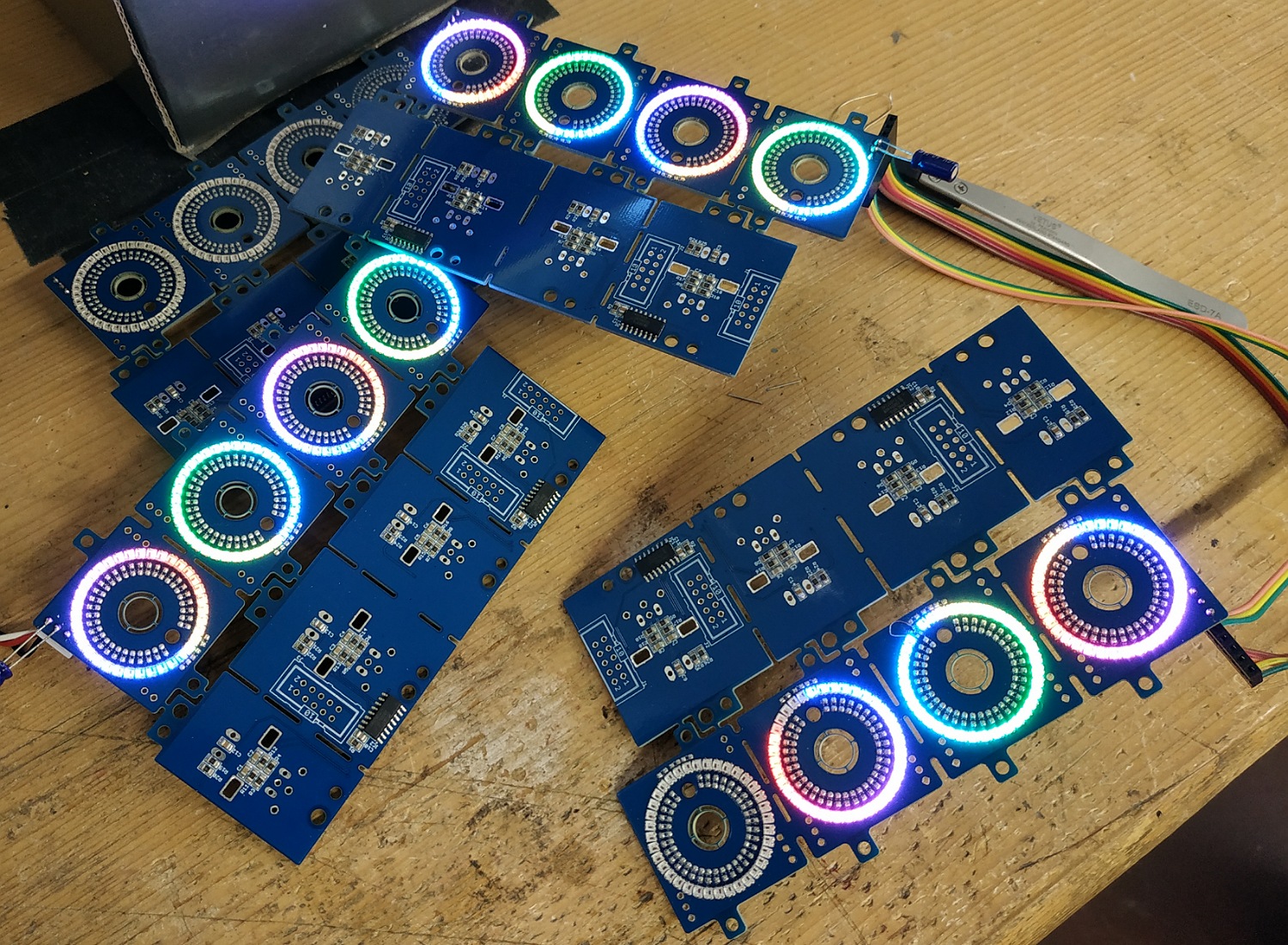
thanks to ! It’s working great.
Anyway I had still some flickering on the LEDs. As I stated above I left away the caps … and this was the reason. I know have added a 10uF on the input and on the output-connector of the LED-rings and the flickering is completely eliminated! Great!!
So, one core can handle a total of 10 LED (10*36=360) rings…
Great work that picture looks absolutely terrific.
we will evaluate the design for a couple more days and run some more tests and then finalize the bulk order with updated prices, anybody interested can PM me now.
edit: fwiw, alternative method of driving ws2812 on the F7DISCO:
https://stm32f4-discovery.net/2018/06/tutorial-control-ws2812b-leds-stm32/
thanks for the coding efforts! This will be very helpful in other projects too.
The rainbow rings look very pretty ![]()
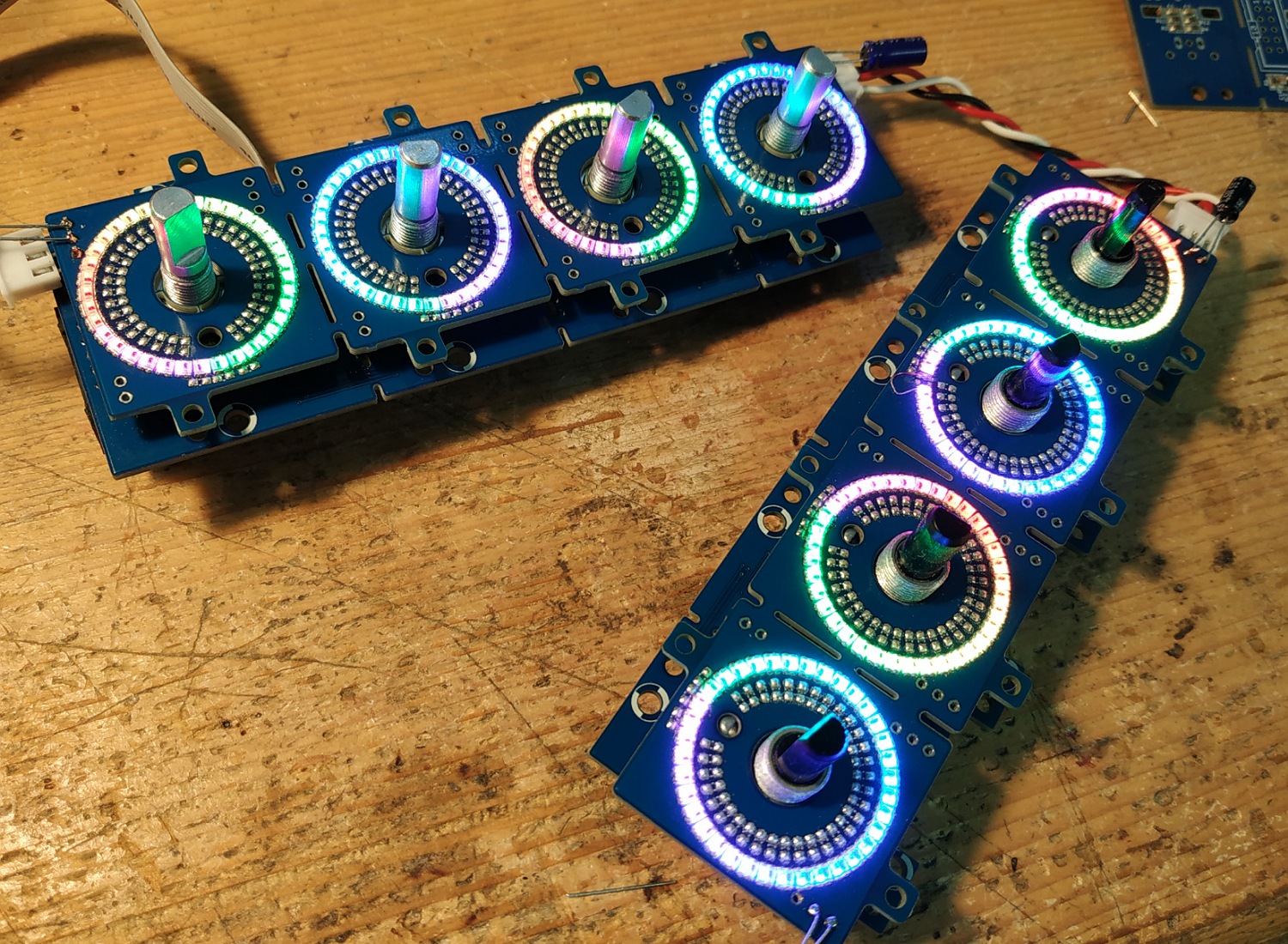
here’s a cute little video with a prototyping frontplate. bottom 5 LEDs are blacked out intentionally for classic “fake poti” use.
this right now is controlled via arduino, not midibox, since there were more convenient demo routines available.
frontplate is 3mm mdf, sitting more or less directly on the ws2812. top row has slightly bigger holes than bottom row. ws2812 running at 25% brightness…
Looks great! ![]()
Yay, Vegas Mode is already implemented!
On 5/28/2019 at 11:34 AM, ilmenator said:
Yay, Vegas Mode is already implemented!
of course, first things first!!
the manufacturer seems to currently have a discount on the assembly parts of the job, so prices will go down a bit! will update asap!
here’s some basic music functionality tests:

I received you message. Tell me what you need to know here as everybody can access it too. If I can answer to your question about what I did for the OLRE16 ring mask and window I will do.
Best
Hey , thanks a lot, good call on the forum post! I feel like this doesn’t belong in the bulk order thread though so lmk if you want me to move this to a new thread before you or anyobdy else answers…
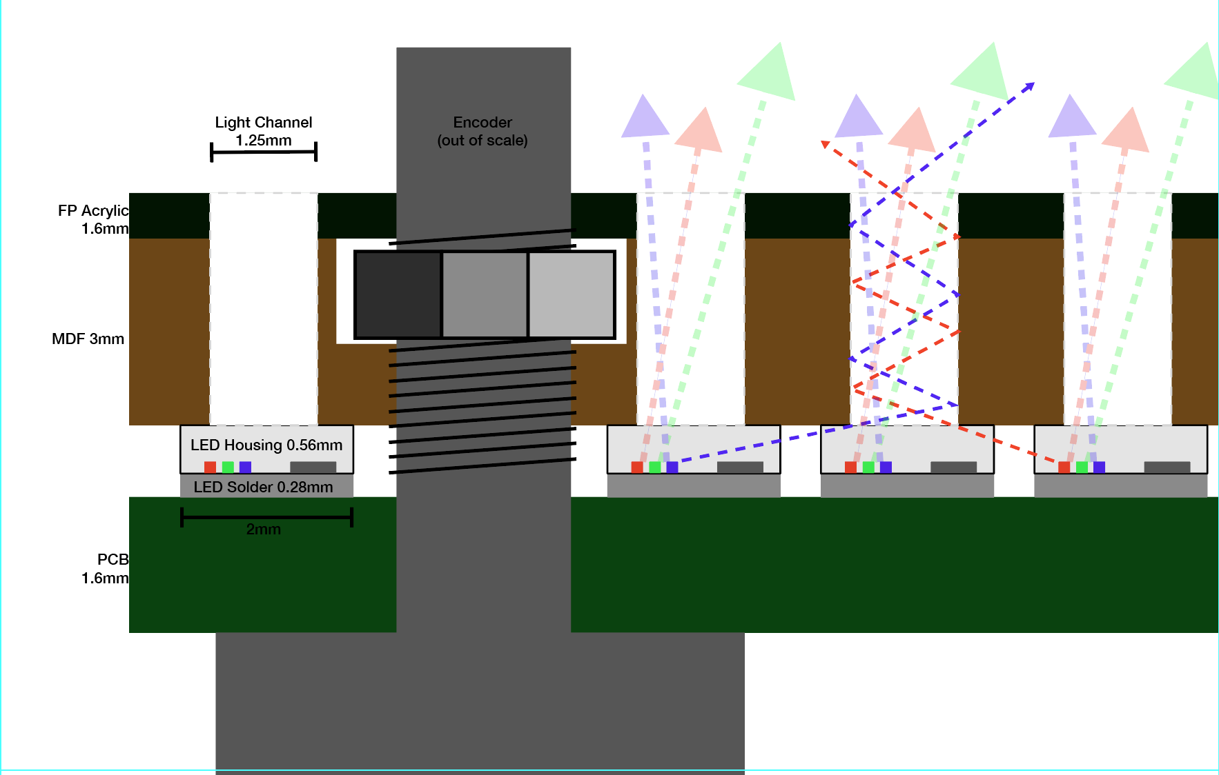
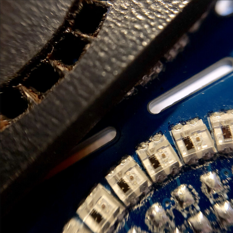
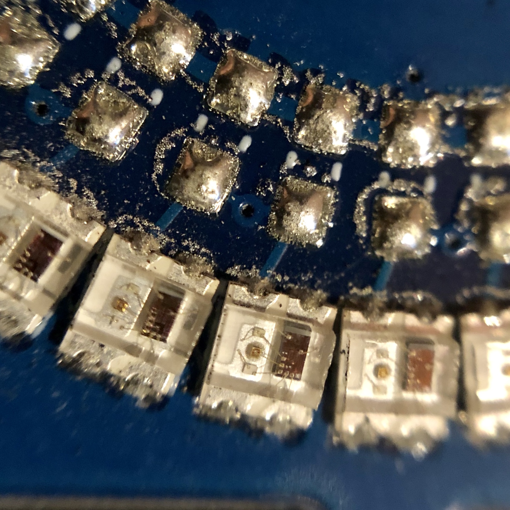
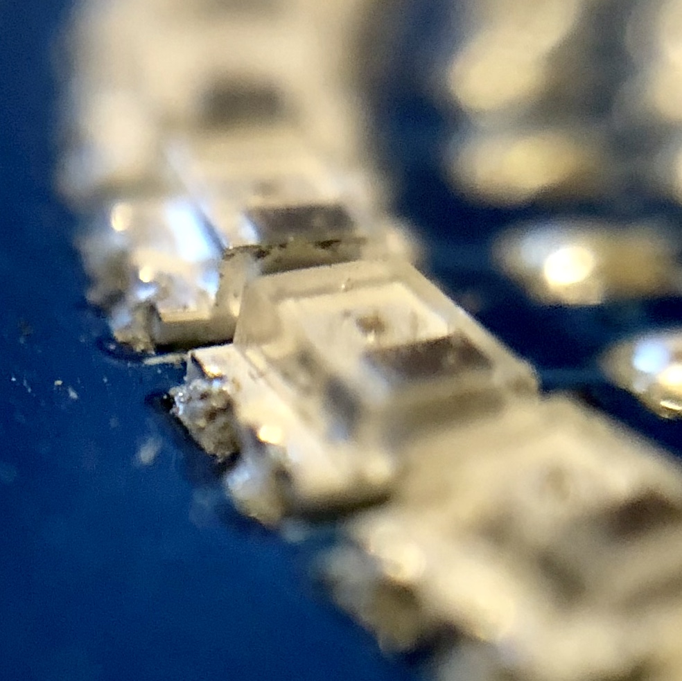
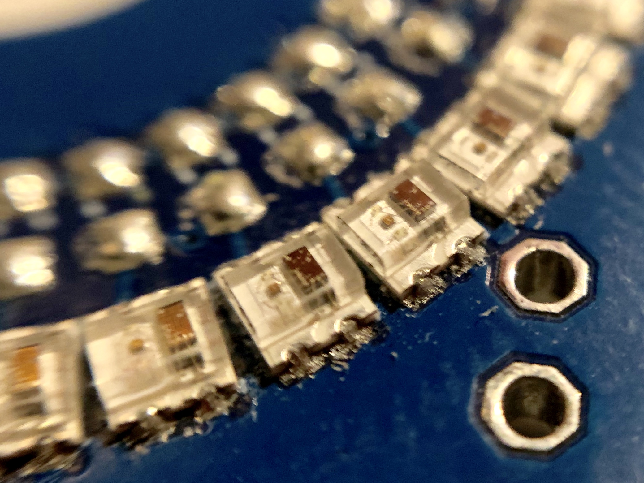
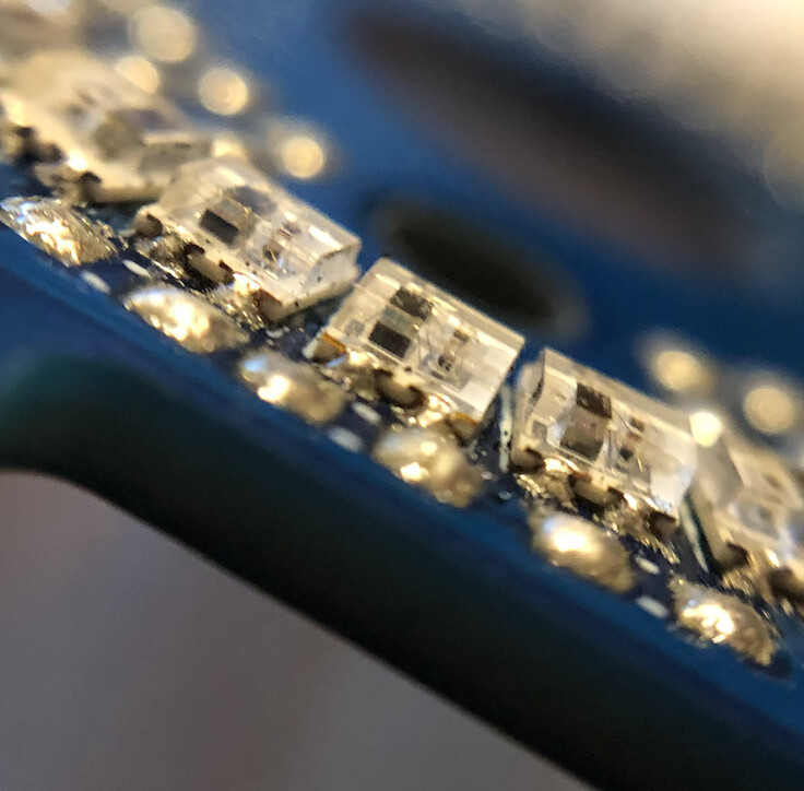
So i am currently investigating frontplate options and i realized some small issues with these 2020 LEDs: they are in a completely transparent housing, as opposed to the white housing with a top lense of the 5050 2812s. So naturally i get quite some cross bleed between the neighbouring LEDs, at highest brightness setting even up to 2-3 LEDs far. In real life it is not nearly as noticeable as on those videos i posted but i am still trying to optimize it.
Then of course i remembered your own glorious LED rings and the transparent inlays you sent me a picture of once. Would you mind in explaining in detail a bit more how you did them and if you think they are viable for my situation?
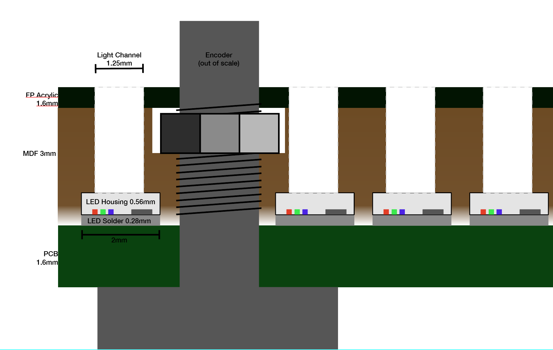
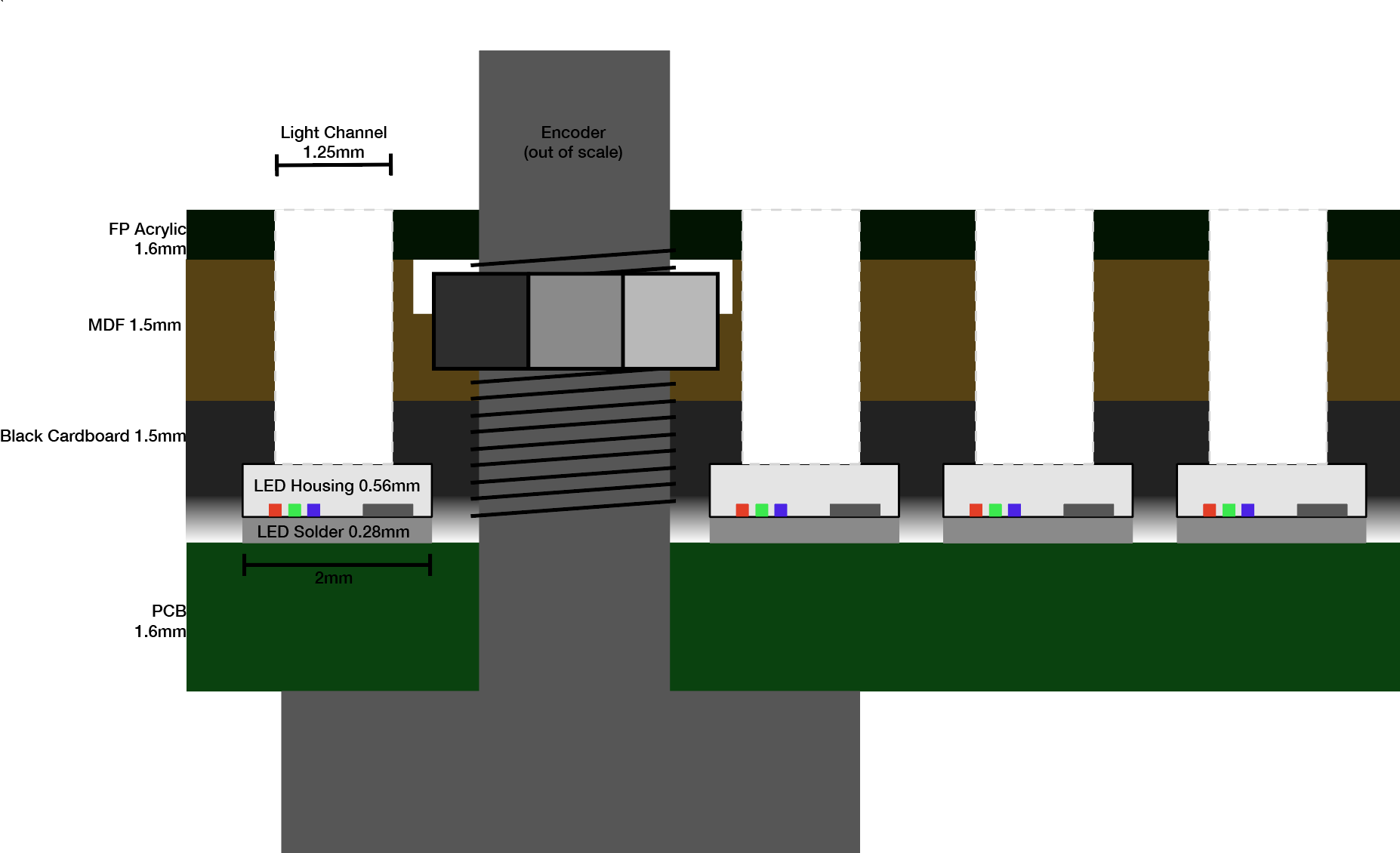
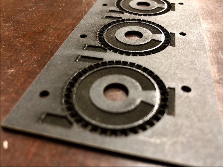
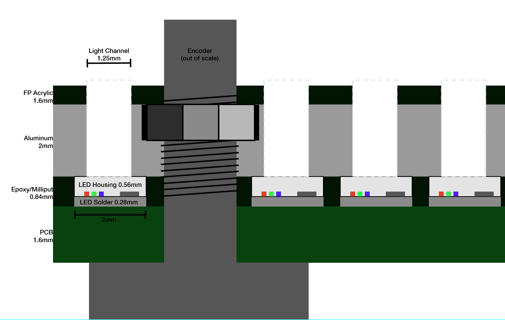
Following are some sketches of what i have so far and some ideas. The “light channel” drill holes got pretty long, 3.5-5mm over all, but that actually makes frontplate assembly super convenient and also should reduce the cross bleeding by creating a more narrow viewing angle. any input is welcome!
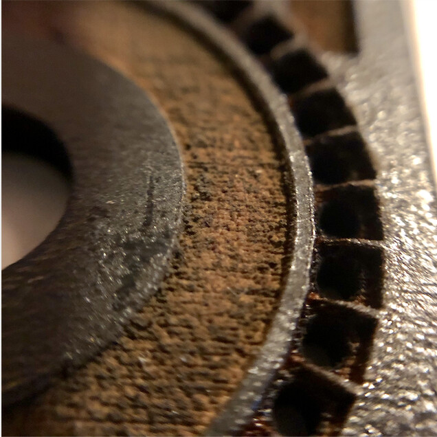
its black coated MDF and obviously the details are a good bit too much for the laser. but i am sure i could still improve on these first tries. it did improve the bleed a little but not to the extend i hoped for.
anybody has experience with using milliput/expoy like this?
another thing to try is the resin-based 3d printer in my local fablab which might be detailed enough to get a better mask going.
and yet one more idea is to get some thick lightproof acrylic paint and a tiny brush and try to paint the sides of the LEDs, or even spray paint it with circular masking tape on the top?
also i am not sure about how to fill the light channels in the frontplate, what you, did so beautifully with those inlays. i was also gonna try just fill them with epoxy and razer off any residue on the outside? or maybe get some 1.25/1.5 mm optical fibre, and stuff each LED hole with a 3-5mm piece that ends directly on the LED enclosure? might also help reduce bleeding.
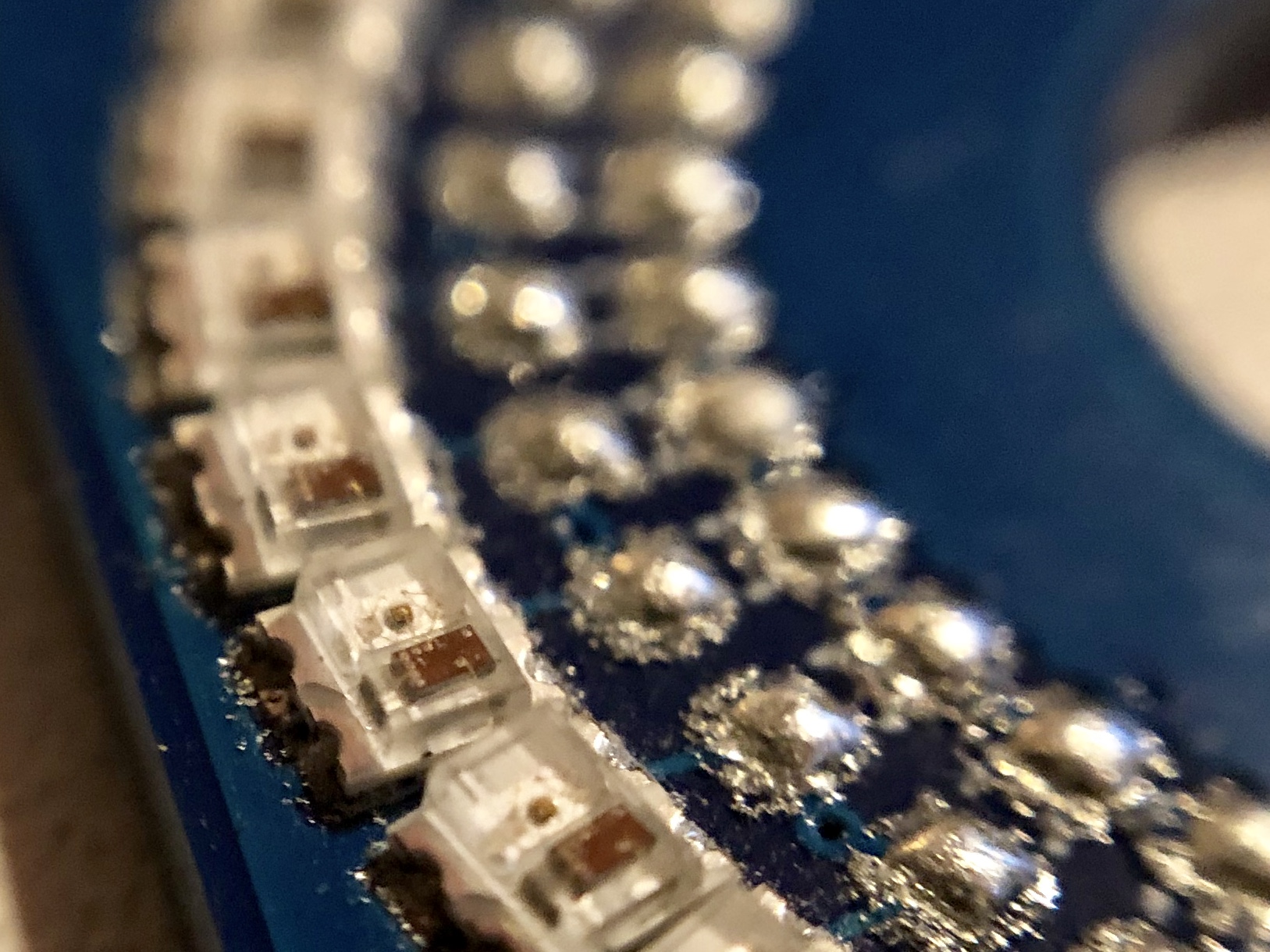
Here are some more pics of 's beautiful prototype SMD assembly job, you can see the shape of the LEDs really good. in before questions: shot on iphone with a 10$ hama macro lens i just bought on impulse at the local electronics megastore. keep in mind these LEDs you see are 2x2.2mm small…
and to lighten things up here’s another video, this time i added some shift functions.

Thanks for your explanation, pictures and videos.
Well, as I told you in an email already you really should think about, going down with the LED-count while keeping the diameter as is now. This will give you some space between the LEDs and it should be very easy creating a mask for it so you don’t have any crossbleeding ![]()