I haven’t got the procedure in mind, but remember the manual is very clear.
I’ve reopen the connectors of my cable, and compare, the diagram is fine.
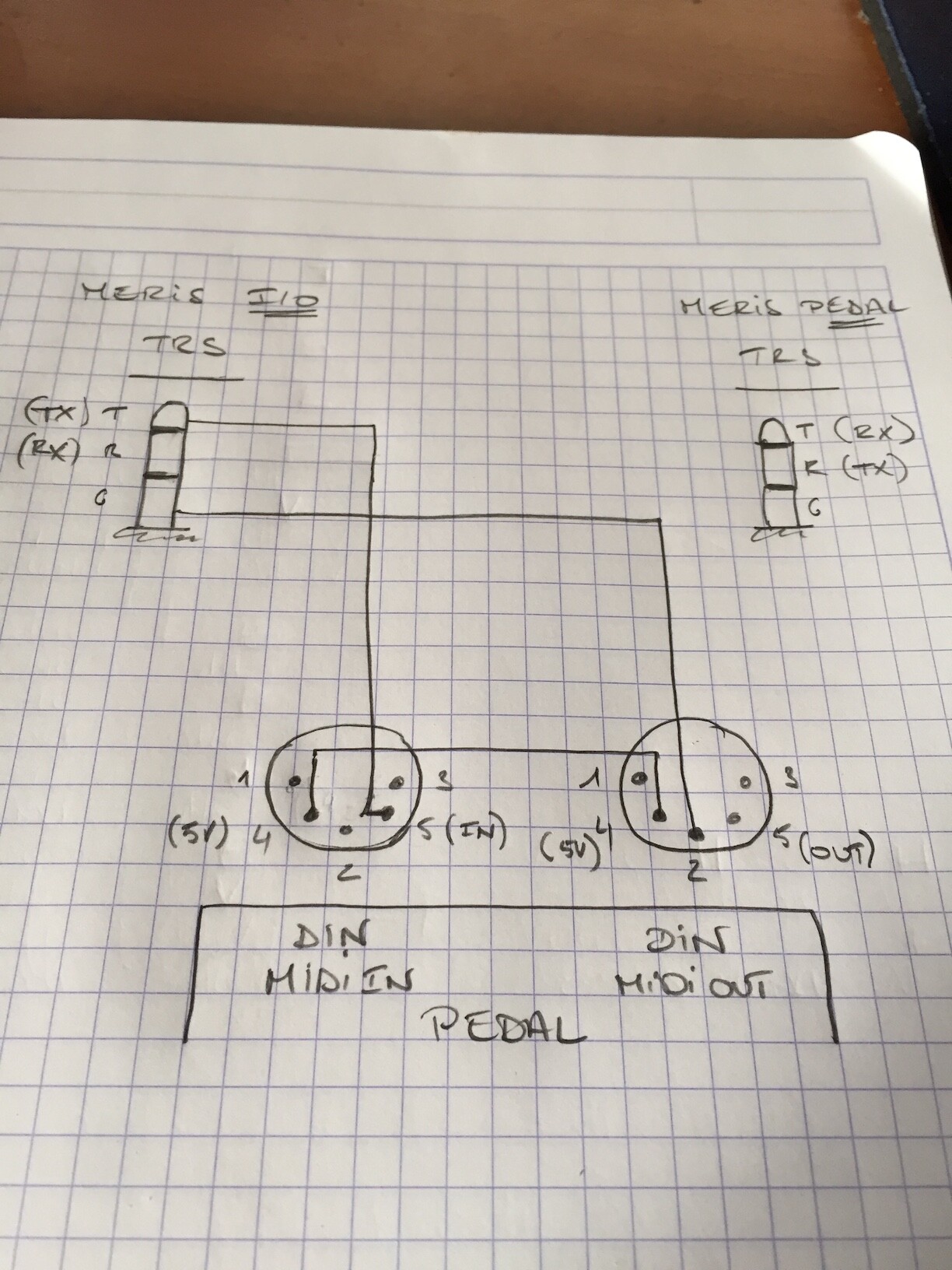
Note: On the diagram,The DIN which has no ground connected(pin 2) must be connected to the MIDI In of your Interface, it’s the Output of your pedal.
Hi all, apologies for the partial hijack of the thread, but I have a question that is somewhat related as I would like to make up a cable that is TRS MIDI out to DIN MIDI in.
What I’m trying to do is to connect up guitar fx pedals to be controlled via MIDI from a Morningstar MC6. The hardware I am using after that, is a Meris I/O, Meris Enzo, Strymon Timeline, and Source Audio Ventris. For space reasons on my pedalboard I’d like to connect each pedal to the Meris I/O via the TRS connections. This is simple for the Enzo as it’s a TRS MIDI IN.
For the Timeline and Ventris, I need to make up a custom cable as the MIDI in on those is DIN MIDI. In my simple understanding, as the Enzo uses a standard TRS to TRS cable it should be possible to make up a cable that’s TRS to DIN, provided I know which connections to make at the DIN end. I do know that the Meris pedals receive MIDI data on the tip (so as it’s standard TRS they’re also sending on that at the Meris I/O) but don’t know how that relates to the DIN MIDI in pin arrangement. Does anyone know how to decode this? Is it not as simple as I think it is?
I’ve been told by Meris that it’s not straightforward as I would need opto-isolator electronics to make it compliant with the MIDI spec. and reliable. I don’t really understand why that’s necessary for TRS to DIN, but not TRS to TRS.
There seem to be some knowledgeable people on this thread, so any information is much appreciated!
Hi,
In your case, best is to keep the Meris I/O for the Meris Pedal only. Meris I/O, Timeline and ventris should be connected directly to the MC6, using a MIDI thu box.
Try to simply do this, the point is to connect the 5V of the MIDI out to the 5V of the MIDI In to get the input optocoupler acting.
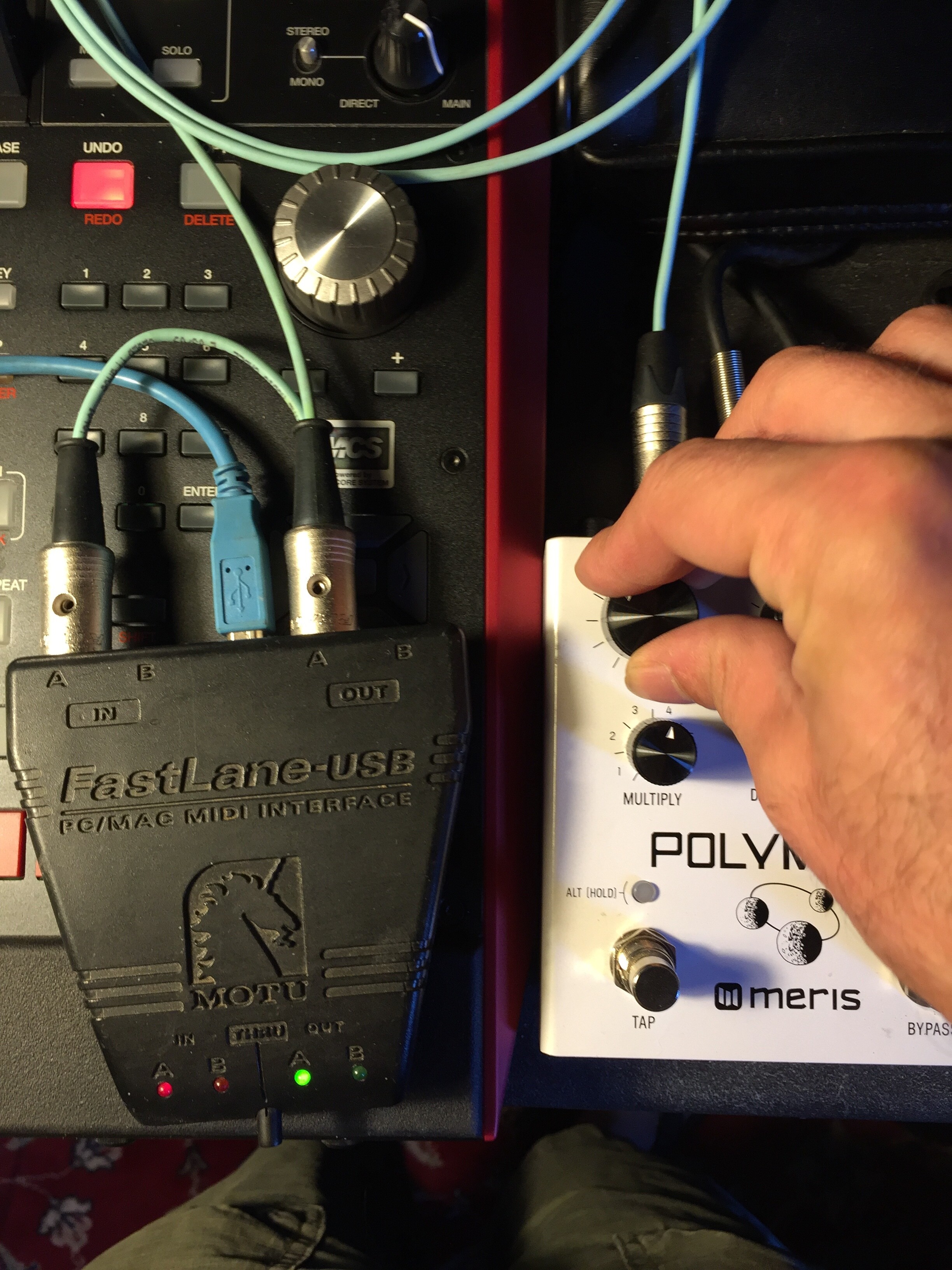
Works fine for me on a Polymoon, receive and send. And cabling example:
Normally the 220ohm already present in your MIDI output acts as current limiter, no need for more resistor.
Best
Bruno
Hi guys,
I’m planning to control my rig (HX Stomp + Strymon Sunset) using my Morningstar MC6 mkii and was wondering if this setup would be feasible for my purposes. I’m trying to avoid buying any MIDI box or Strymon EXP MIDI cable.
This post is just a feedback because I couldn’t find anyone that actually built it.
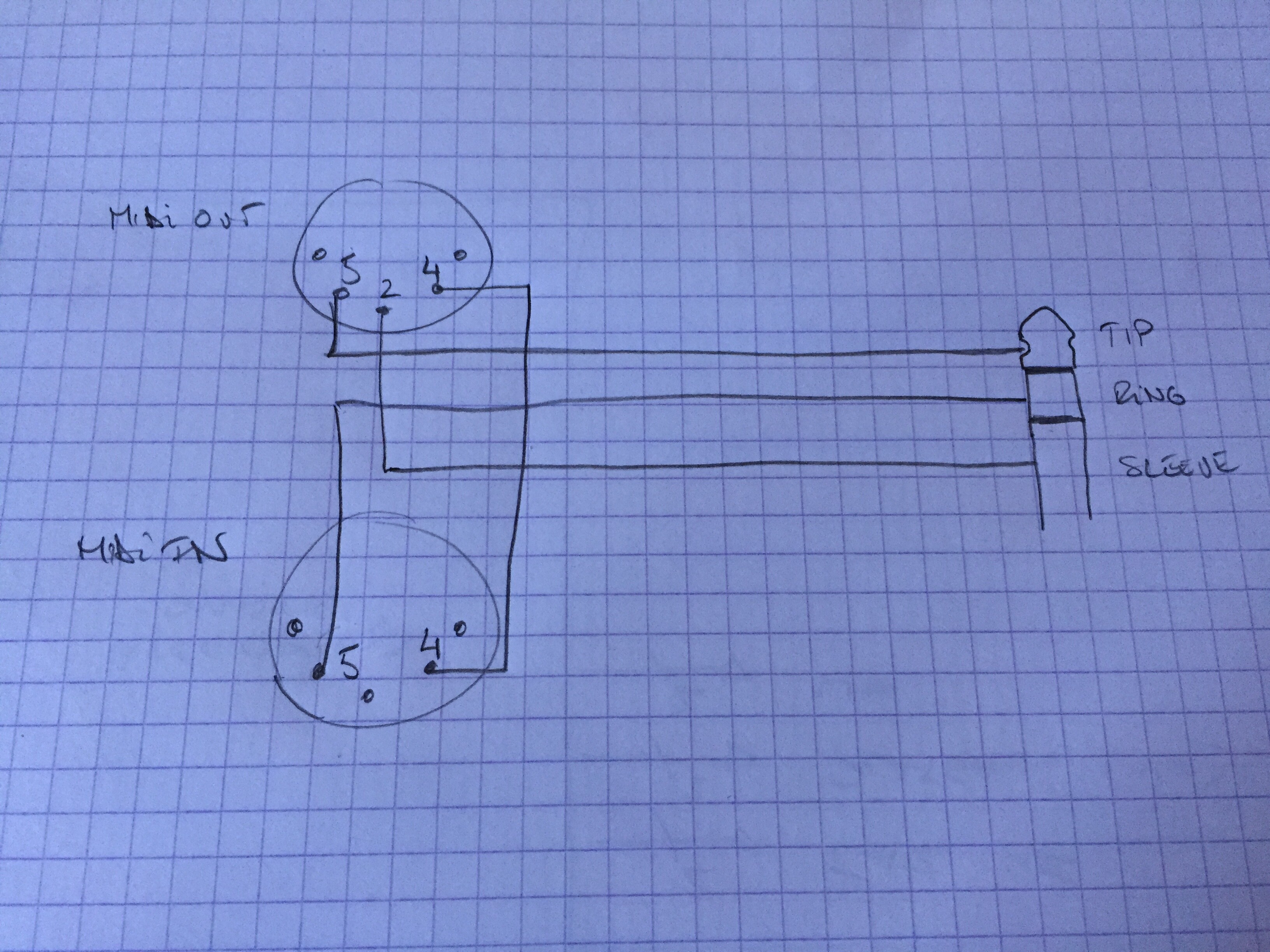
I just built the midi din to TRS jack from this schematic: https://imgur.com/gallery/Md24LCE?s=sms .
The only information missing was that the 5V on the diagram must be connected to the ring of the TRS jack. 5v comes from the pedal receiving midi datas.
And yes, it works perfect with my Strymon Iridium.
This post is just a feedback because I couldn’t find anyone that actually built it.
I just built the midi din to TRS jack from this schematic: https://imgur.com/gallery/Md24LCE?s=sms .
The only information missing was that the 5V on the diagram must be connected to the ring of the TRS jack. 5v comes from the pedal receiving midi datas.
And yes, it works perfect with my Strymon Iridium.
Hello,this diagram is a regular MIDI input stage, it’s not a passive circuit and must be powered, if you connect the 5V to the ring you will get issue when the pedal send data. The ring is the TX point which has idle state at 5V but 0V on data transmit and use it as a power source is also not a good idea, it’s a CMOS/TTL signal.
Hello,this diagram is a regular MIDI input stage, it’s not a passive circuit and must be powered, if you connect the 5V to the ring you will get issue when the pedal send data. The ring is the TX point which has idle state at 5V but 0V on data transmit and use it as a power source is also not a good idea, it’s a CMOS/TTL signal.
If you are right and and the ring from Strymon jack midi port is not a 5v power supply, it means that power should come from din phantom power from the midi controler or another pedal. I understand it means midi din port with 7 pins.
However Strymon pedals with midi din port are 5 pins only. I can no believe that their own cable would not work between their own pedals.
That’s why I don’t think that you are true and I think that Strymon use a non standard midi over jack pin out with 5v power coming from the slave pedal on the TRS ring and no TX capability.
- https://www.strymon.net/midi-control-sunset-riverside/ , Hugo (Strymon’s customer support manager) wrote in the comments " As for MIDI IN and OUT, this is done via the EXP jack with the pedal receiving (MIDI IN) MIDI messages at the TIP and sending MIDI back out (MIDI OUT) at the RING of the TRS connection. As the Strymon MIDI EXP cable does NOT support bi-directional communication, you would need to get a device that accommodates for MIDI IN and OUT using a single TRS cable such as the Empress Effects Midibox2. "
-> Strymon MIDI EXP cable does NOT support bi-directional communication
My conlusion is that if The Strymon pedal is set for midi out configured as ON or TROUGH it is just like you said (TRS ring is the TX). If it is configured as OFF it is just like I said (TRS ring is the 5V power supply).
If it is configured as OFF it is just like I said (TRS ring is the 5V power supply).
If it’s configured as OFF the signal just stays in idle state, it does not switch as a power rail, it stays a logic signal. I suppose this was made strong, depends on what is inside, logic buffer, transistor, cpu pin directly, depends on the current it can support;
What I wanted to do here, is avoid any interface box and get IN and OUT, and it works fine with a Merris.
With your solution you just recreate this interface box(regular optocoupled midi input) and power it with a logic line from the pedal and without Output.
Here the original and well known diagram of a regular MIDI IN and Thru.
This thread talks about how to replace The Empress MIDIbox by a simple cabling.
This product is from the Empress brand, and has just the same name as our forum.
This thread talks about how to replace The Empress MIDIbox by a simple cabling.
This product is from the Empress brand, and has just the same name as our forum.
I am asking basically, referring to all sorts of “Midi Boxes” and I do talk about a simple cable replacement.
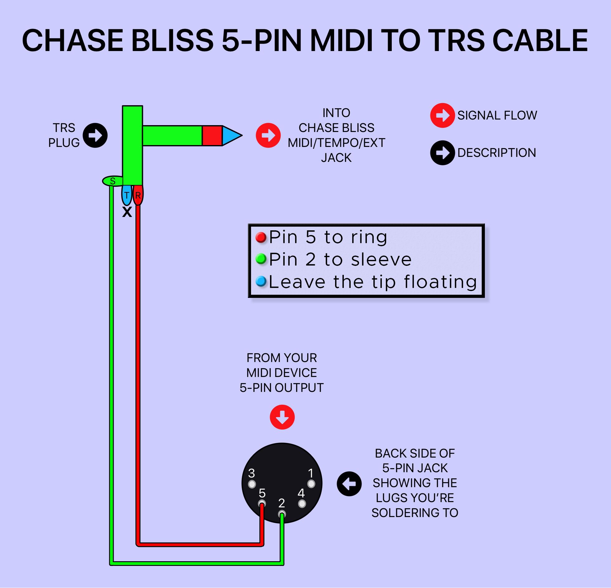
I have the basic information about the Chase Bliss specs and soldered a cable that IS SUPPOSED to work, but it doesn’t - and before I buy a box that costs 20 times of a cable I need to know what’s the deal with it
Could you show us what you did, cabling pinout and the basic information you got in hand to do it?
With basic information I mean that I am aware of all Chase Bliss quirks and requirements. Also I have been in contact with them and did guided troubleshooting.
My controller is a MusicomLab EFX MK-V that works perfectly well for sending Midi PC and CC messages to other pedals such as a Line 6 M5 or Boss 500-series through ISO
I have connected the CBA Tonal Recall with a self made MIDI-TRS cable to the MIDI out of my EFX MK-V (specs attached). Cable is tested with a multimeter. Midi Channel supposed to be correct.
Did you try to receive something from another machine(computer) to the chase bliss with this cable?
Maybe pin 2 of your controller is not connected to the ground internally. Pin 2 is a shield and it’s normally not used on the receiving side(MIDI In), some manufacturer don’t follow the rules and don’t connect it.
Try with another MIDI Out device, if it works then open your MusicomLab controller and add a piece of wire from a ground position to the pin 2.
Great idea. I will try that.
Just to be on the same page: given that would be the case, could it make sense to rewire the Midi plug instead of messing with the controller? Since the ISO cables work well, and they are likely grounded on pin 2. Or do ISO cables just don’t need a ground?