Step 8: Adding Encoders!
Part** s used:**
(* 17 pcs Alps 12mm encoders (with push-button function)
http://www.reichelt.de/Rotary-Pulse-Encoder/STEC12E08/3//index.html?ACTION=3&GROUPID=3714&ARTICLE=73923&SHOW=1&OFFSET=16
These 12mm encoders are not recommended anymore, especially, when used with a STM32F4 based core. They have a different pinout, and while the “DETENTED1” decoding method works in many cases (and flawlessly on my LPC17 board), sometimes the encoder values jump back. If you have already soldered in these encoders, see the second page for an easy fix (swap middle and right pin with wires).
)
**OR **
* 17 pcs Alpha 16mm encoders (without push-button function)
Mouser P/N 318-ENC160F-24P
Note:
* 16mm encoders are a bit easier to install - but need precautions with the datawheel encoder - see below.
* For this build, I preferred the 12mm encoders for three reasons:
- I have used the exact same type of Alps encoders in my other SEQ since ~4 years - they are rock-solid and have never let me down (but the Alphas in my MB6582 are really solid too, even after years of use, so this is no real argument! :-)).
- They offer “pushability”. So you can add “temporary push acceleration” - which is really handy, when adjusting parameters with only one hand available. Both encoder types will have a resolution of 24 steps/clicks per turn, which would allow for an octave of note adjustment per half-turn. Now, when you are able to push the encoder, you can configure the MBSEQ to multiply this effect by a given factor - for example allowing for three octaves of note adjustment instead per half-turn. I experienced the benefits of this feature first on the Elektron Machinedrum - and grew used to it - up to the point, where I wanted to push the encoder in my car radio to speed up the volume adjustment :-). Of course, there are other (pushable) encoders available - but I only wanted to list these two encoders, because they never failed me (both Alps and the Alphas).
- These encoders are a bit smaller, allowing us to “top-solder” the datawheel encoder. This is not advisable with the 16mm encoders, where the datawheel encoder needs to be soldered to the underside of the PCB, otherwise the big datawheel “dial” will be elevated too much above the frontpanel.
* If you decide to go for 16mm encoders, you might jump to the next step (LEDs) now and come back to this step later. It will be a bit easier to solder the LEDs first. But when using 12mm encoders, I´d recommend to solder them before soldering the LEDs, because we need to top-solder the encoder pins, and that would be difficult with the LEDs already installed.
Description:
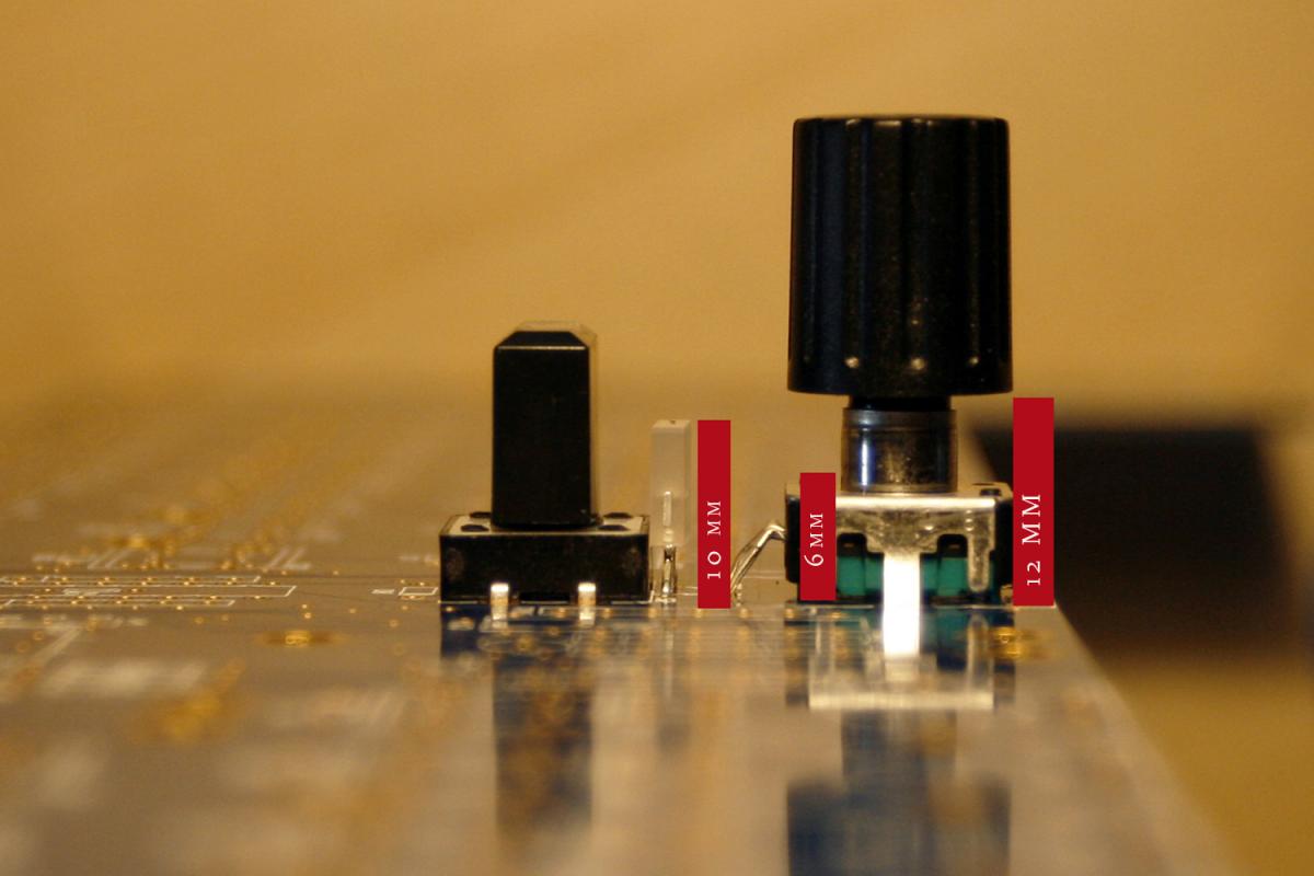
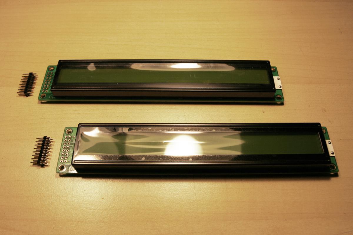
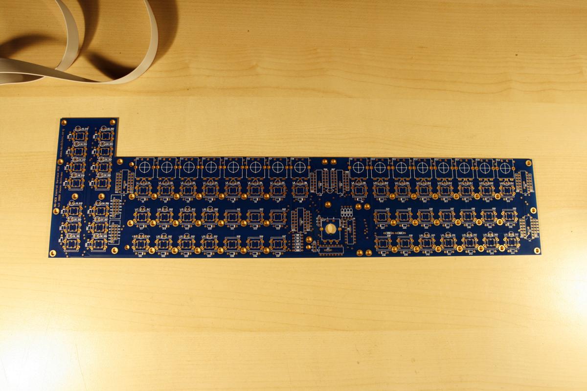
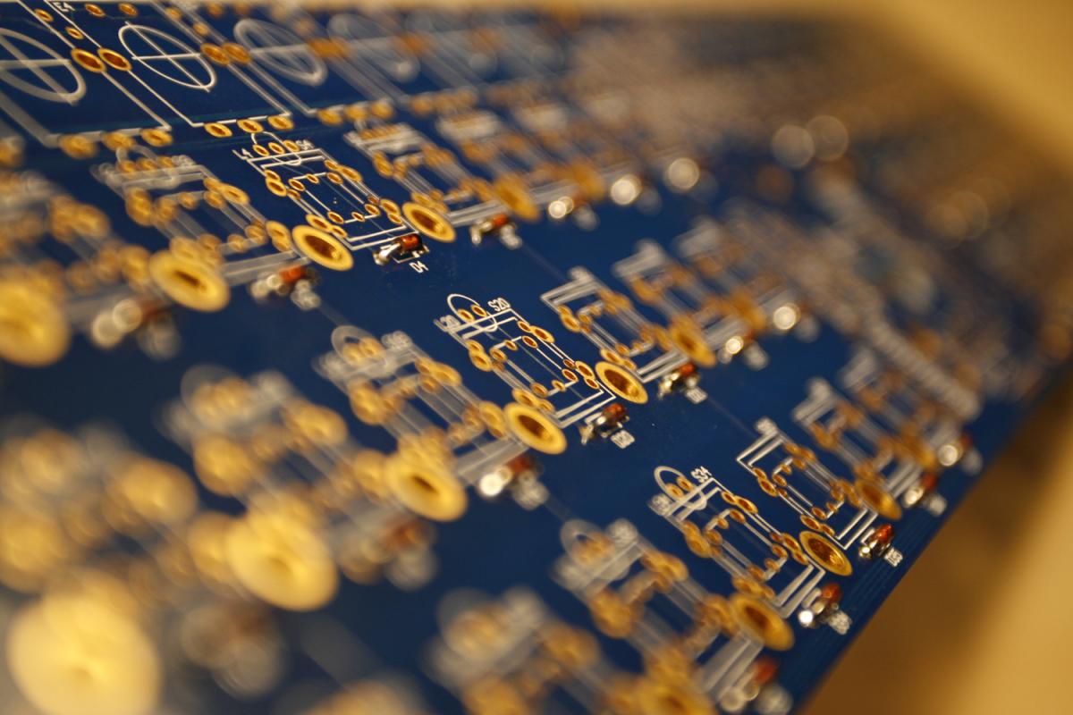
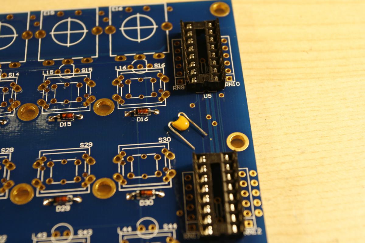
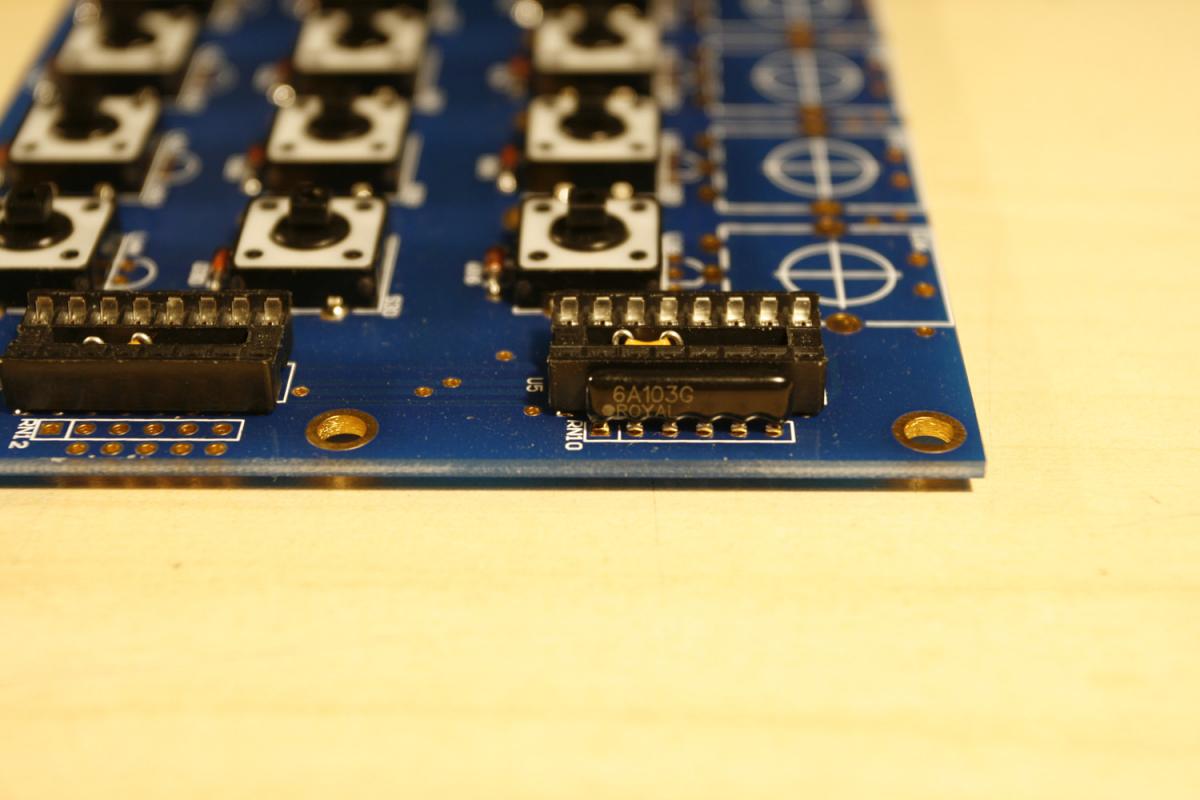
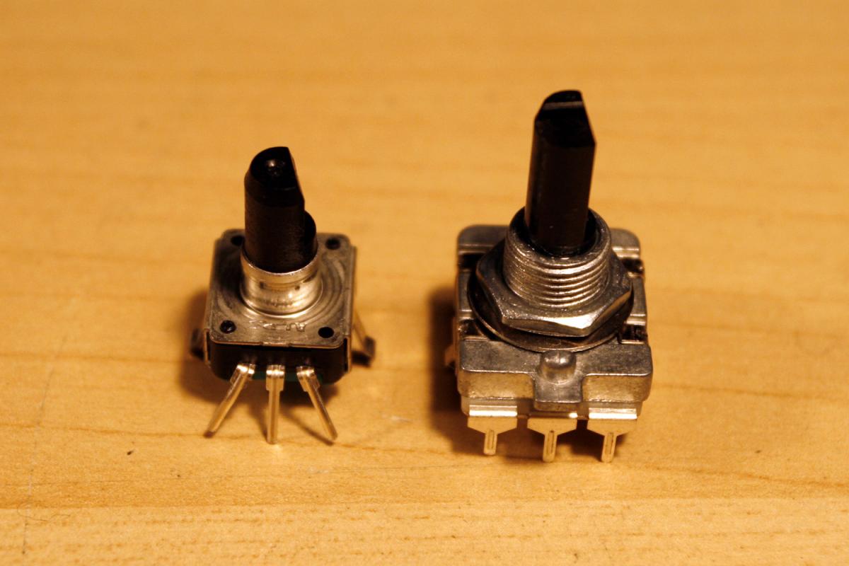
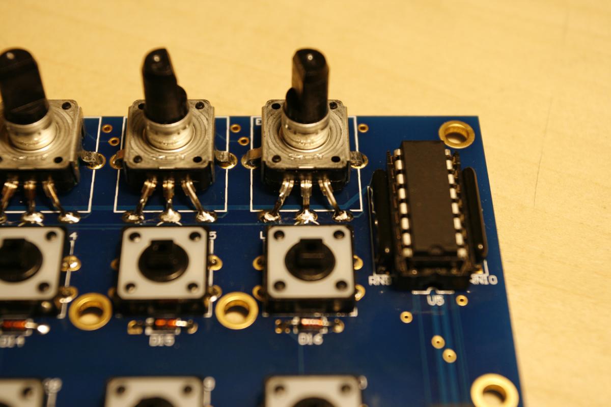
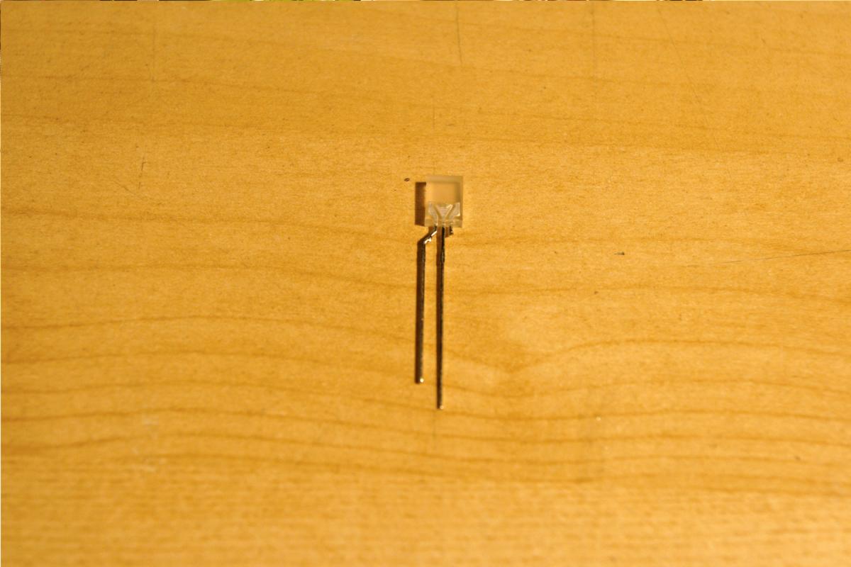
* Choose your preferred encoder type - 12mm or 16mm? Both will fit (after a bit of adjustment for the 12mm type) - see photo 1.
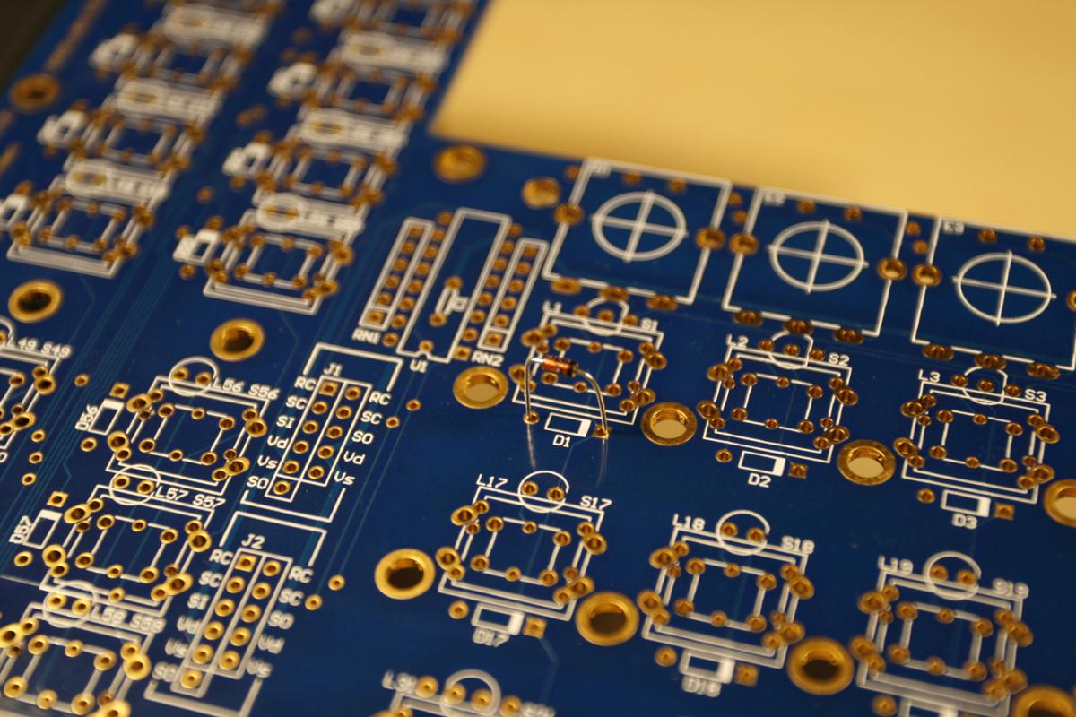
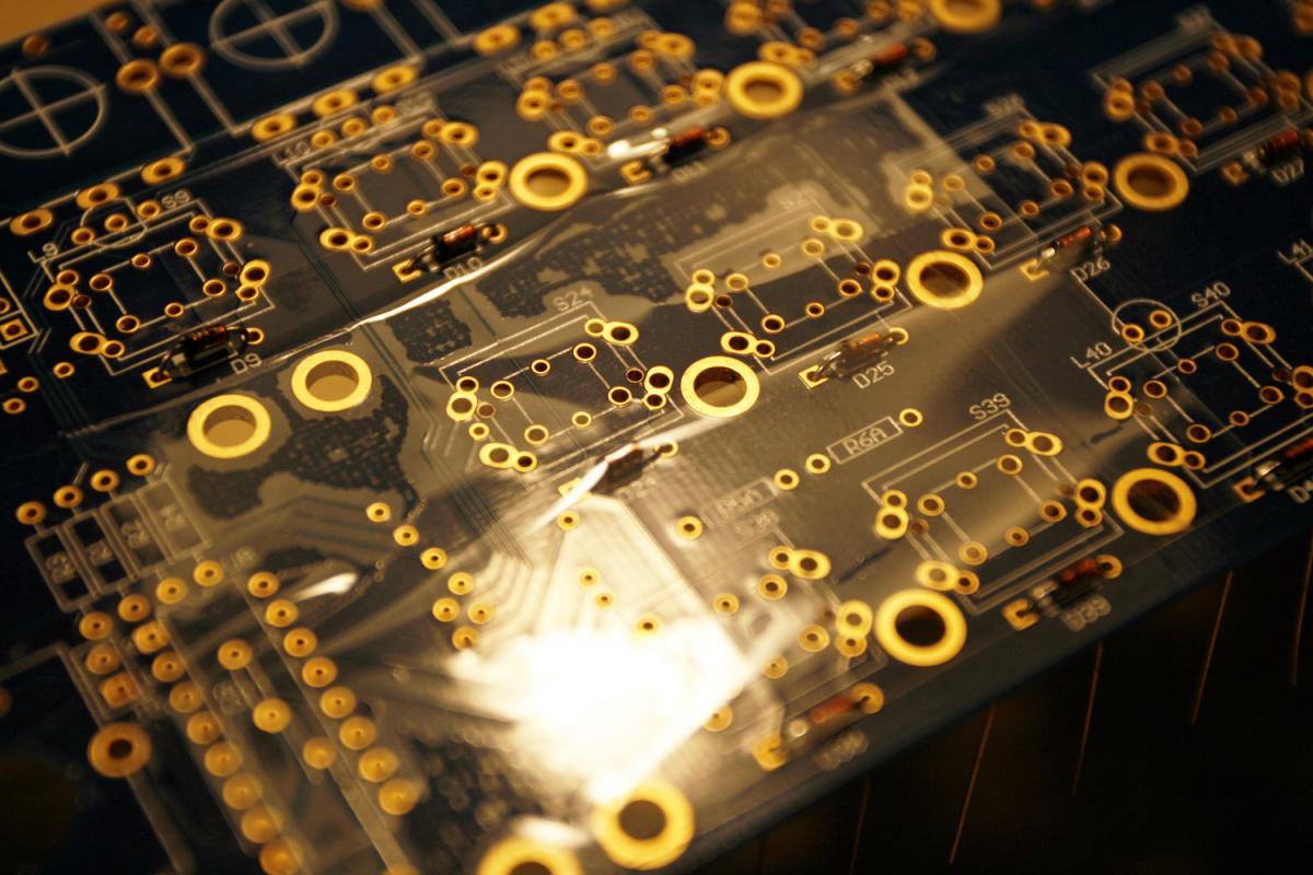
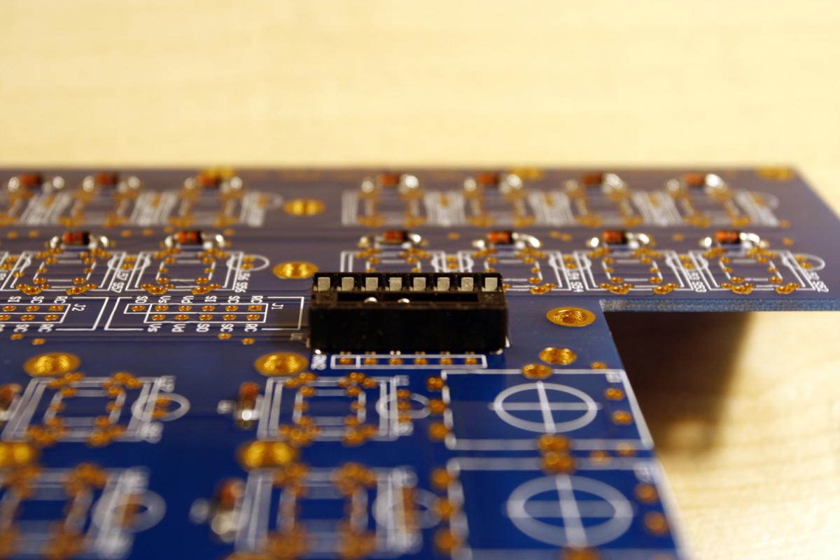
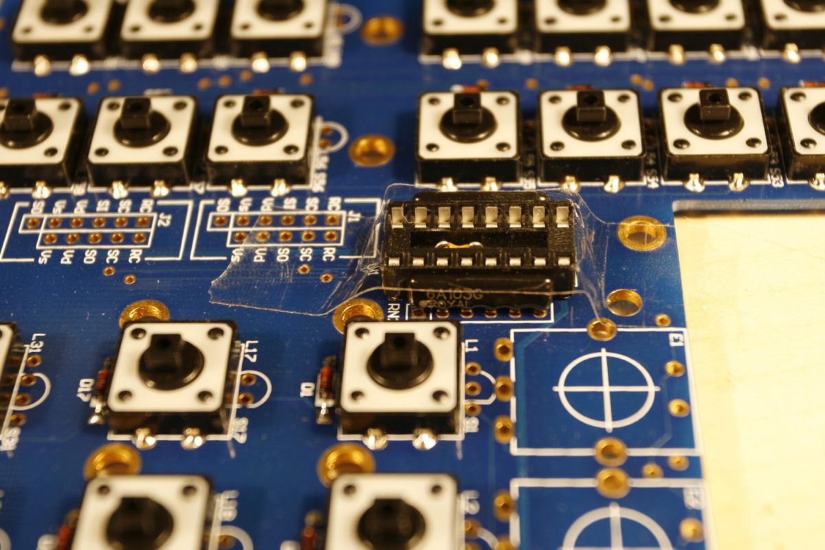
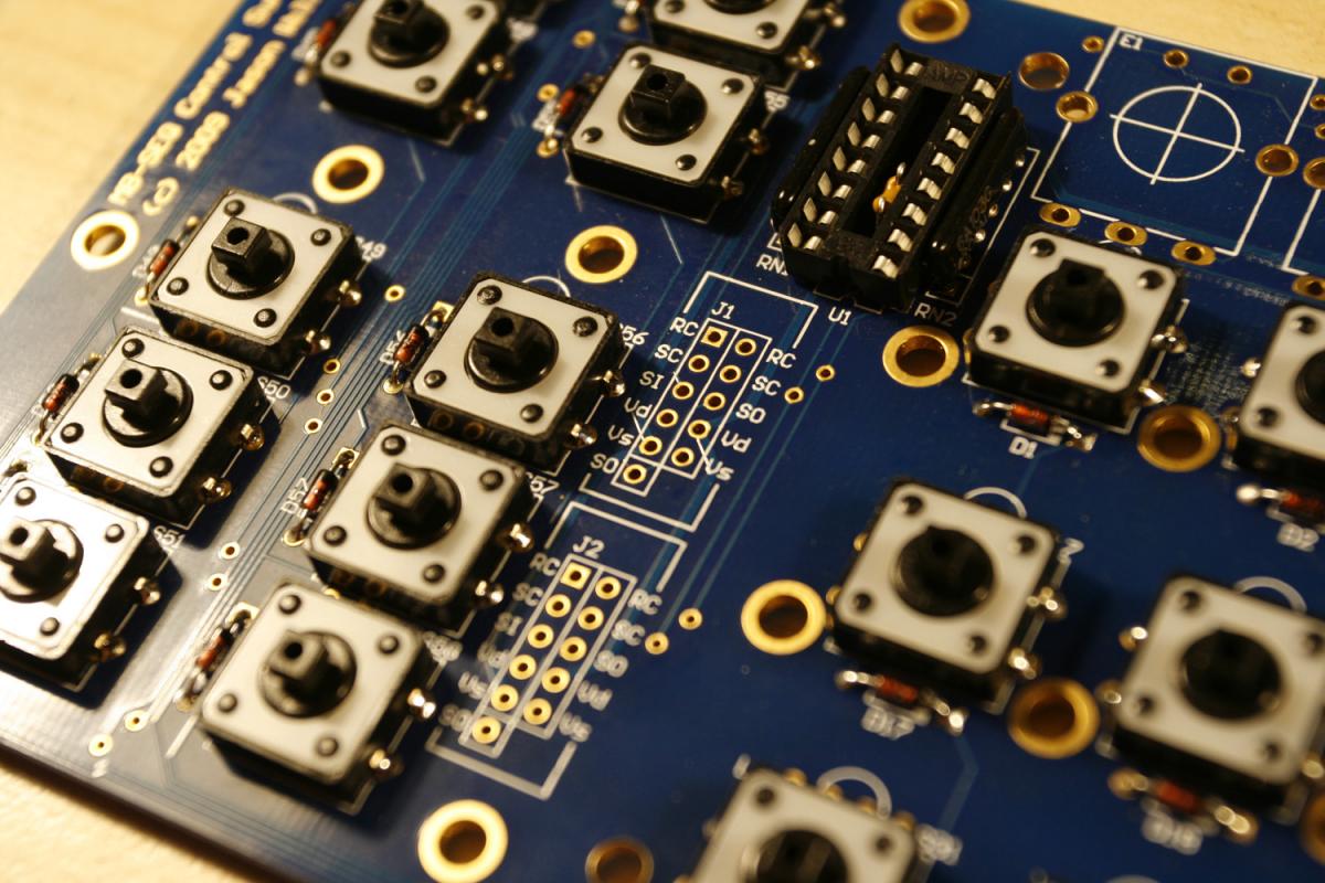
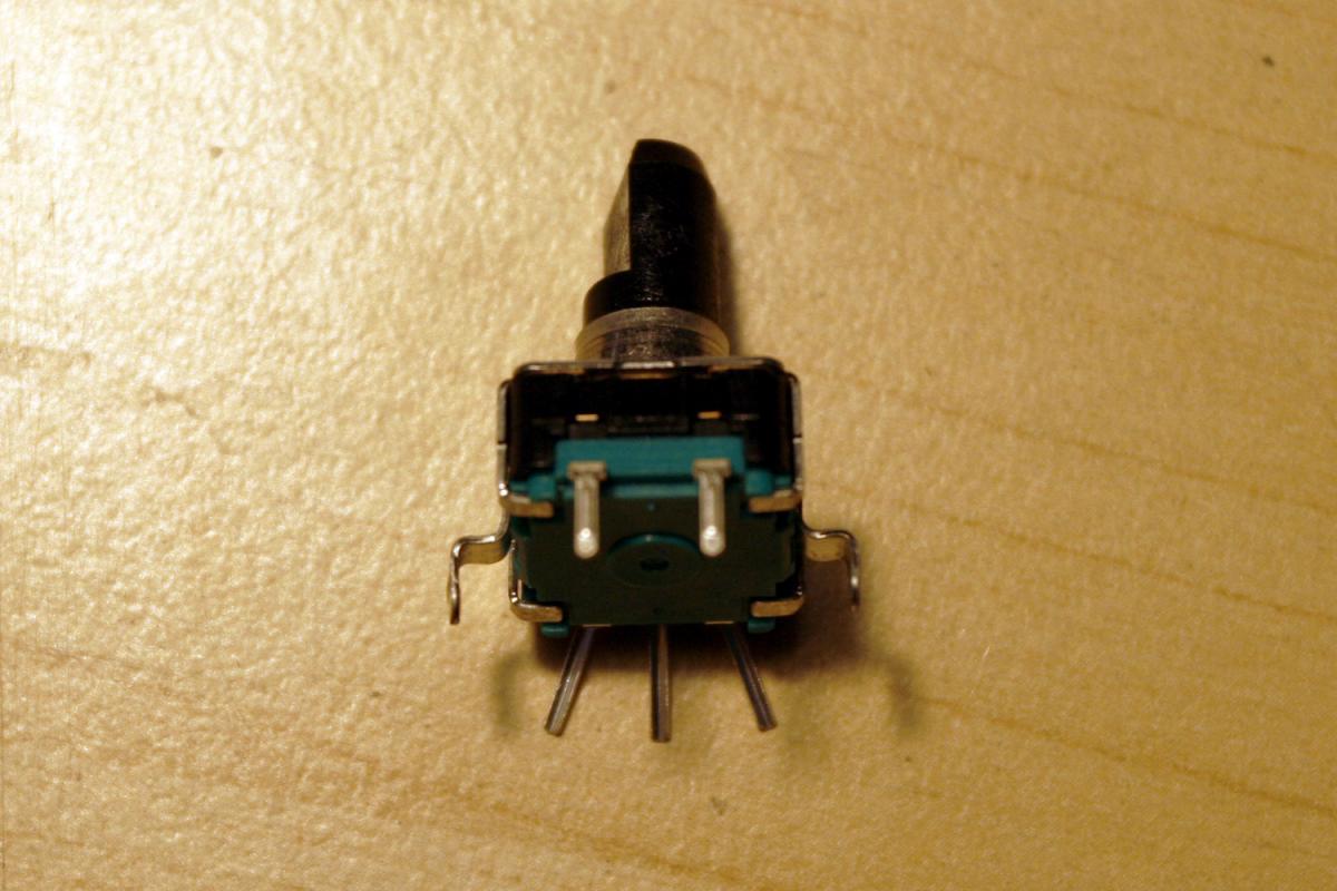
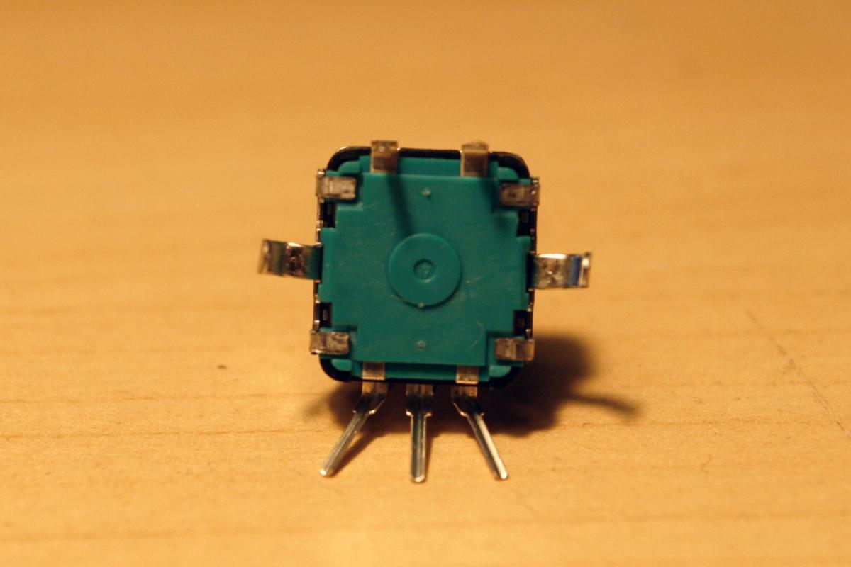
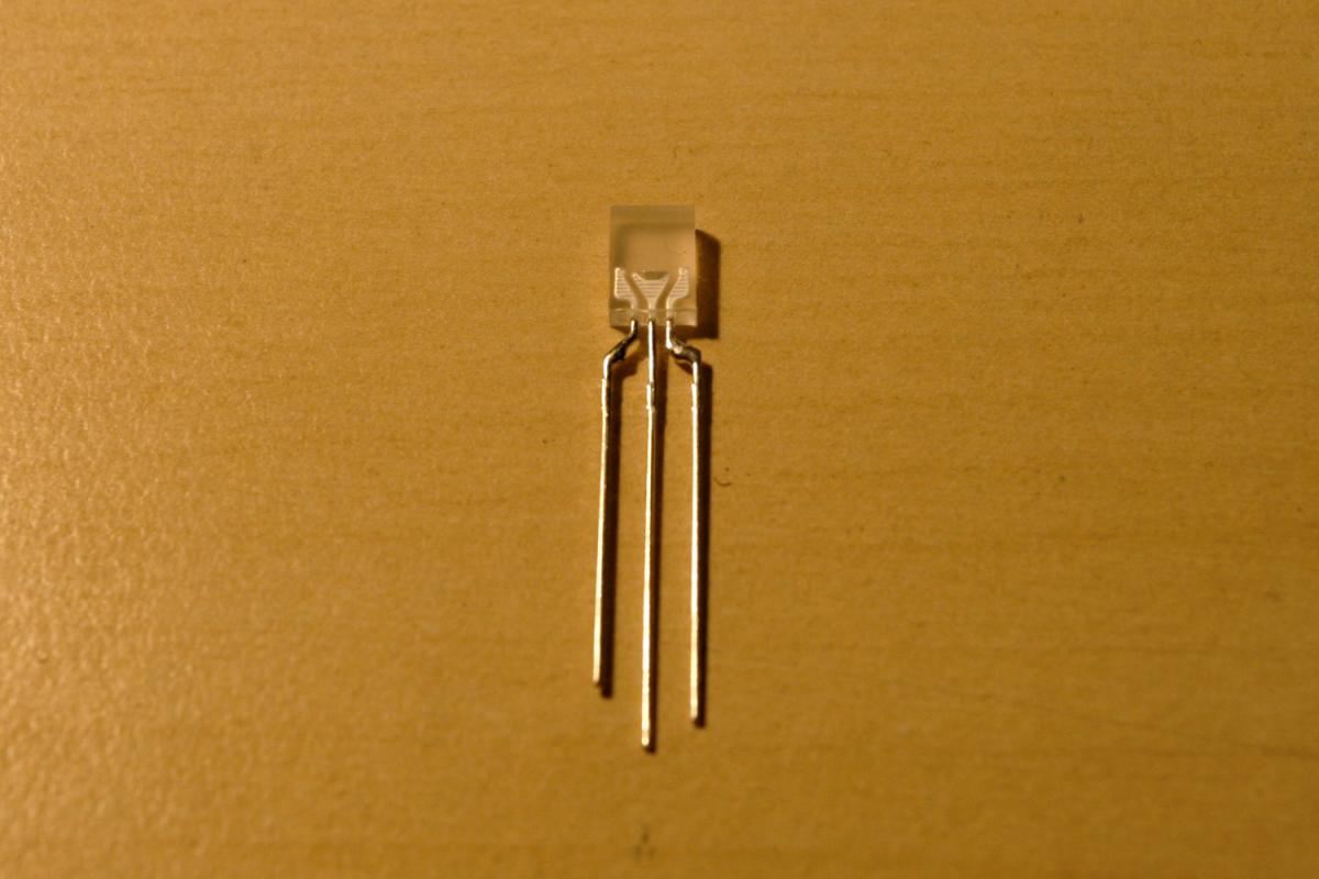
* If using 12mm encoders, they need to be bent with a caliper. First straighten the notch on the center metal “fastener” pins. Then bend them at a 90 degree angle (parallel to the bottom of the encoder). Then bend them back in a 90 degree angle 2mm away. After a bit of training, this will work without problems and will only take about one minute per encoder - see photos 2 and 3.
* Also, you need to bend the three main encoder pins a little bit - see photos 2 and 3. Do not bend the upper two (push-button) pins - they fit perfectly and allow us to properly align the encoder.
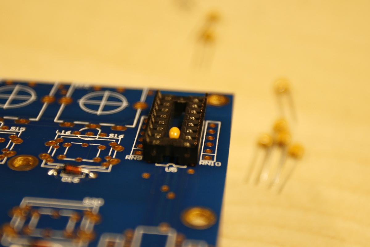
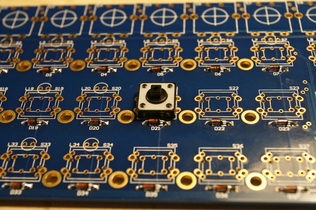
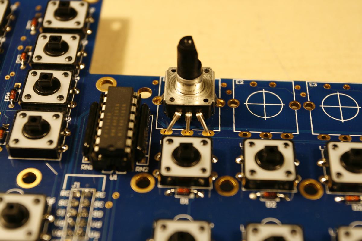
* To install the encoder, insert the lower three pins first, then click in the middle “fastener” section, then the top two pins - see photo 4.
* No use of force is necessary - the encoder will just “click in” - if that does not work, go back to the bending steps. It is not too difficult (re-examine photos 2 and 3 in case of problems) 
* After installing an encoder, check its alignment and also make sure, that the encoder base is pressed flat to the PCB. When done, solder the backside (3 encoder pins, 2 push pins and 2 fastener pins).
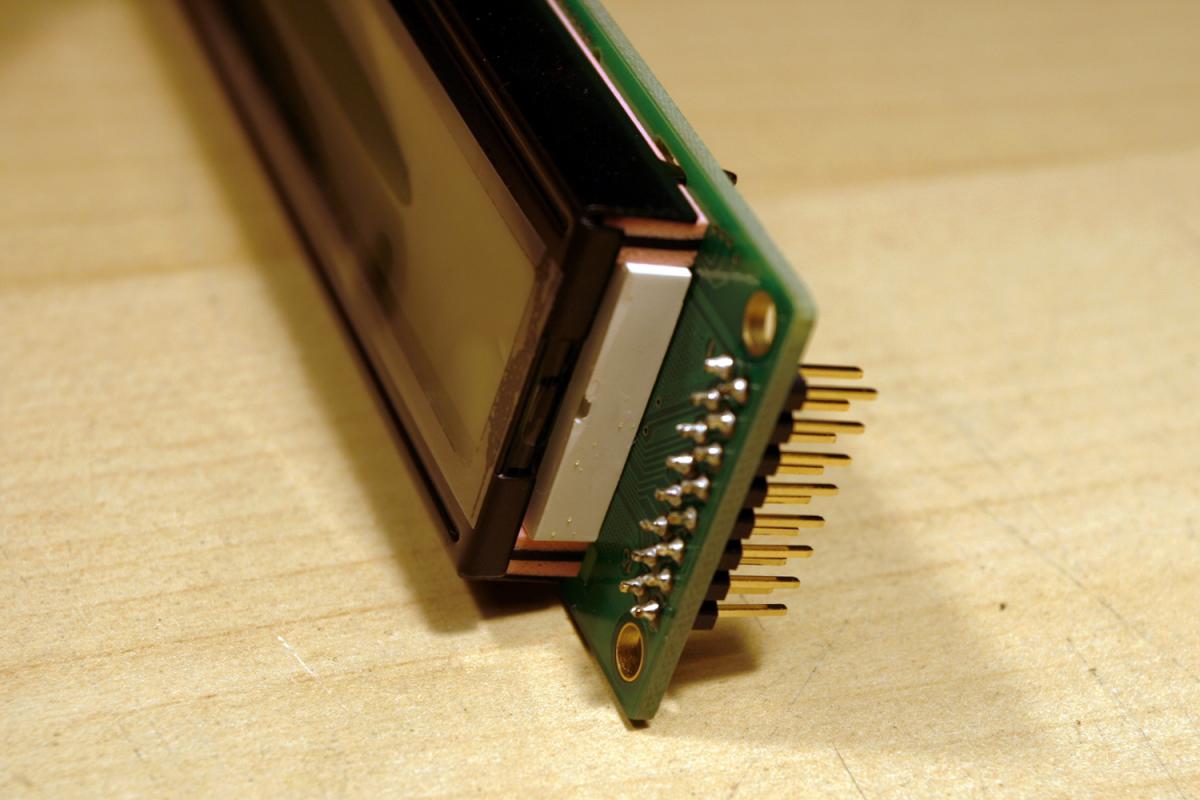
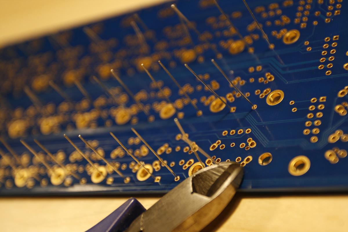
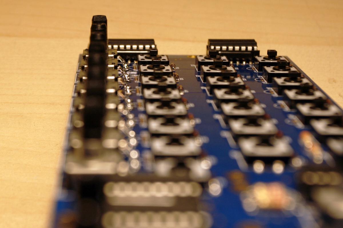
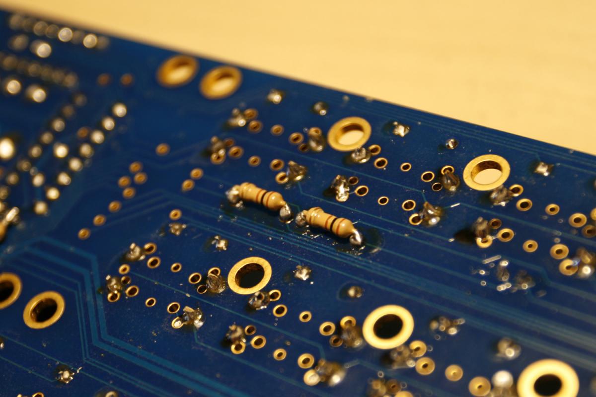
* Turn the PCB over and solder the three lower encoder pins from the topside (photo 5) - this is necessary, as the left and right lower pins may not be long enough to reach through the PCB to the bottom - and we want to ensure a proper connection.
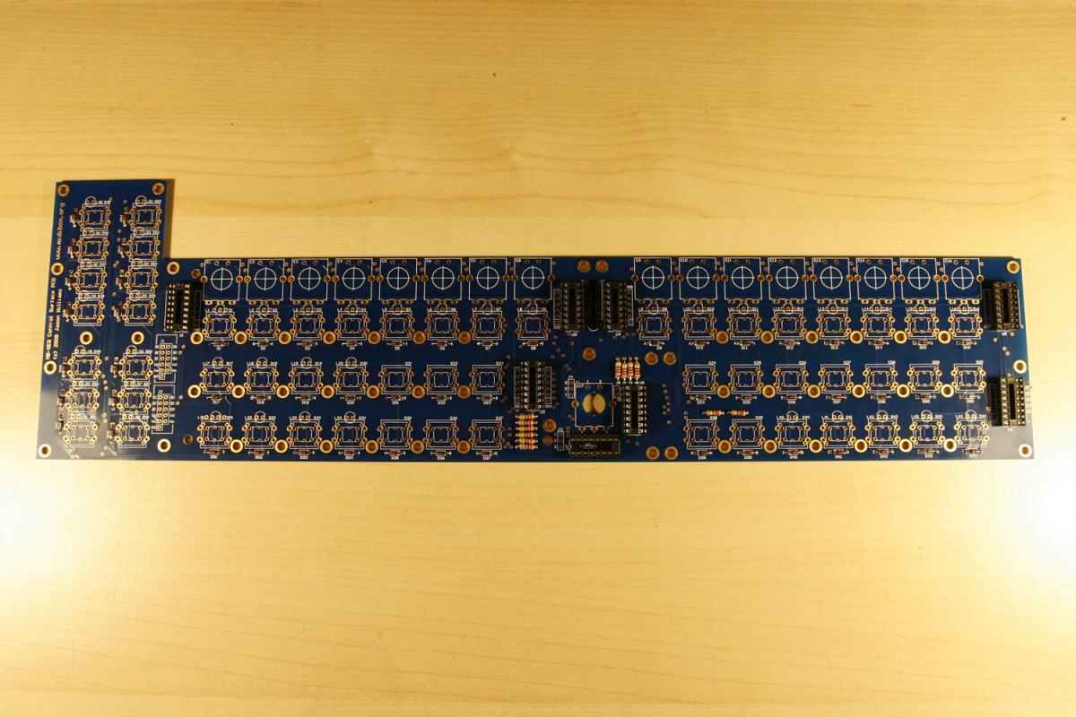
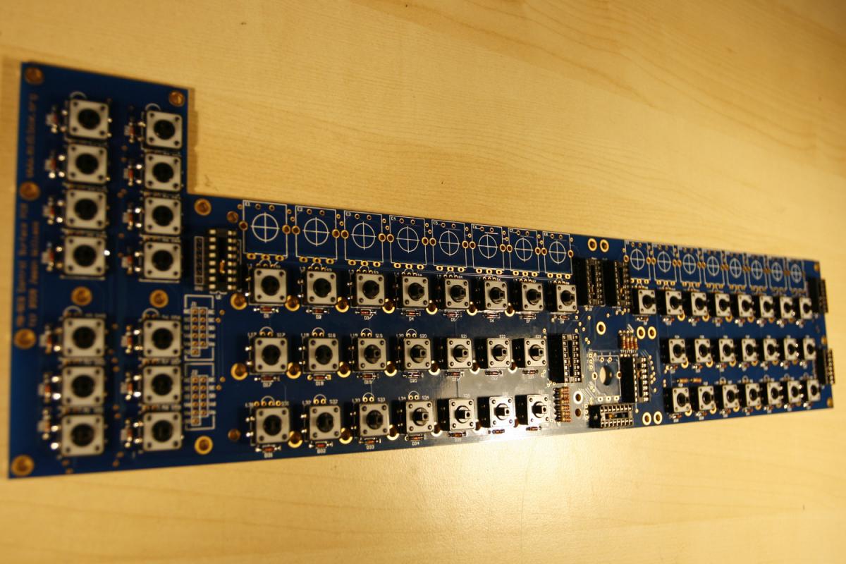
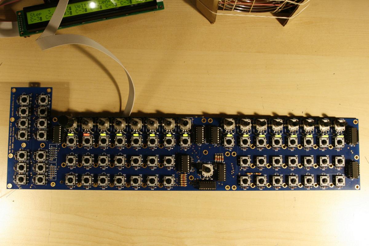
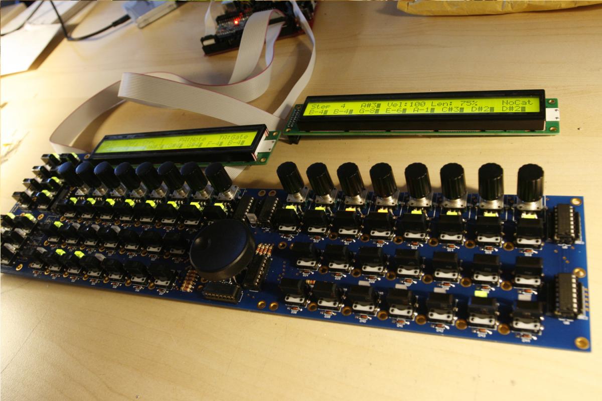
* When all is done, your encoders should be aligned nicely - see photo 6.
* To enable “push to accelerate”, open the MBSEQ_HW.V4 file (on your SD card) with a text editor and search for the line
BUTTON_FAST2 0 0
Change that to
BUTTON_FAST2 6 0
Also, i´d recommend to set
ENC_AUTO_FAST 0
which will enable FAST2 mode for note entry on the standard note layers, when the encoder is depressed.
And:
ENC_GP_FAST_SPEED 5
to increase the encoder speed a little bit more, when the encoder is depressed (The default is 3).
For the Alps 12mm encoders, please also change the encoder type to DETENTED1 throughout the file:
ENC_DATAWHEEL 6 2 DETENTED1
ENC_GP1 1 6 DETENTED1
...
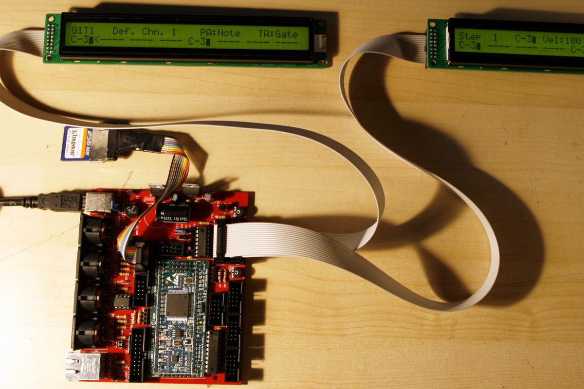
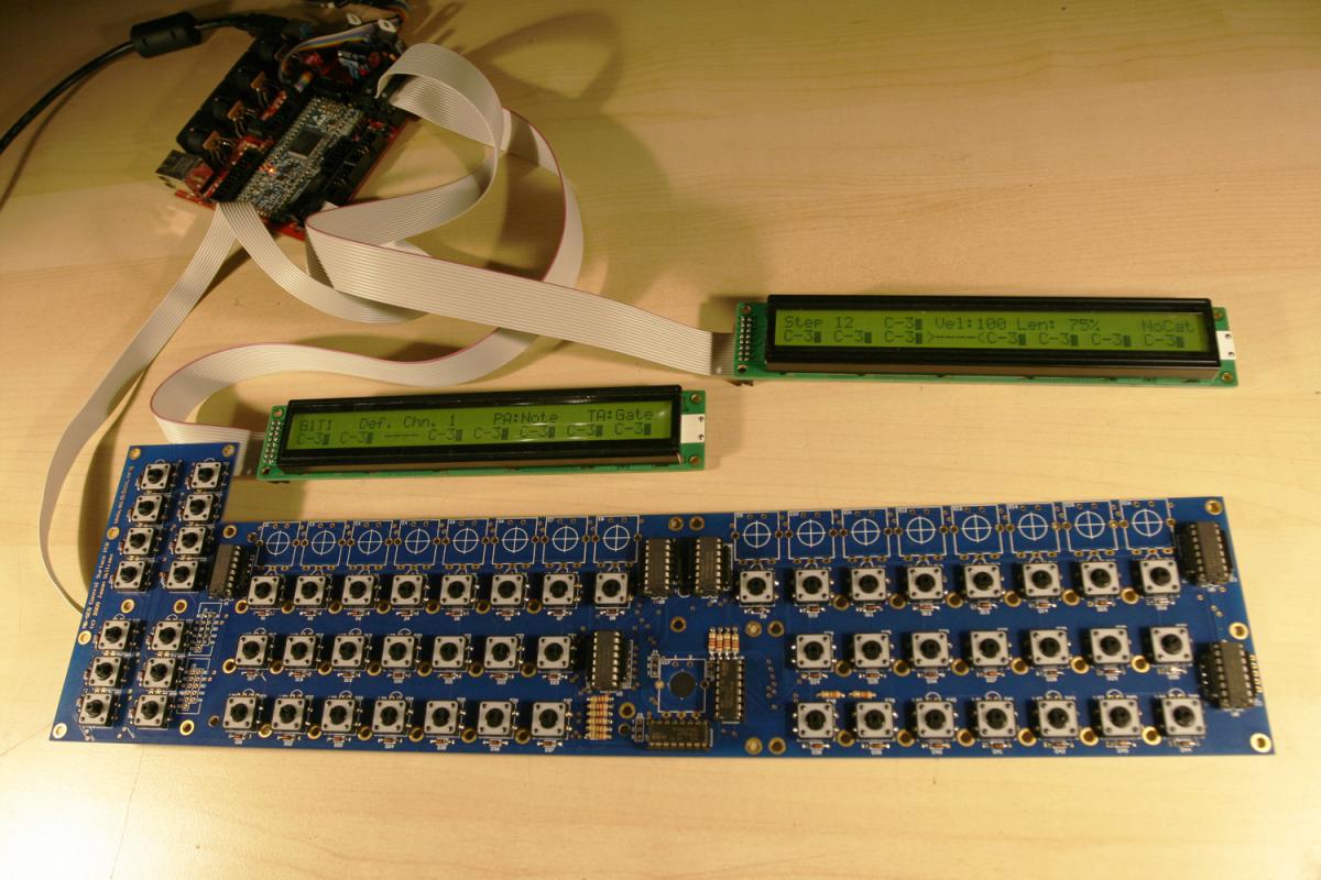
Now save the file, insert the SD card in your SD card adapter and restart the MBSEQ.
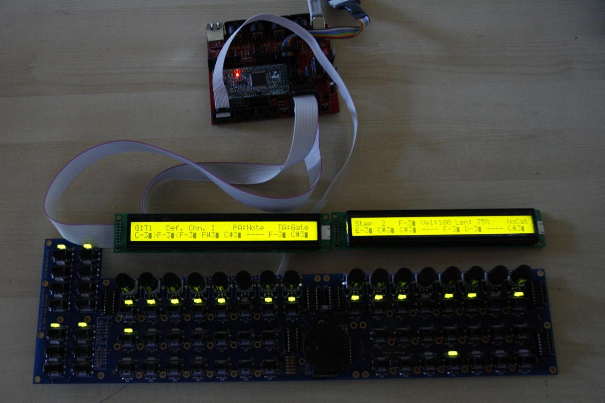
You can now test all encoders and the temporary push acceleration - a really *very* nice feature - thanks again for implementing it, TK.!