first of all: thanks to TK for all your great work!!
so i finally got a seq v4 and soldered everything yesterday.
i got a MBHP_CORE_STM32F4, Wilba SEQ CS board and MBHP_MIDI_IO.
i used the wilba MBSEQ_HW.V4 file without any changes and the newest firmware version (088)
no magic smoke after the first power up, but not all the buttons are working. only step 6,7, 10 ,11 of the step buttons are working and some of the other buttons also do nothing. (i didnt check which ones exactly, because i am unfamiliar with the user interface and never sure if every button should do something in the menu page i am in)
the encoders all work fine.
i didn’t solder the leds yet, because the panel is not ready and it will be easier to get them in the right position if i do them later.
i did check the solder joints visually and the orientation of the ics on the CS Pcb -no obvious problems there.
my roommate also build a unit for himself and we sourced all the parts together. his unit has the exact same problem.
thats why i think it is not a simple solder error like a short or wrong orientation of some part. (because that would be unlikely to happen twice.)
please help me with troubleshooting. i don’t really know where to start looking.
i am a midibox noob by the way. (only did a seqv4lite in the past) so it is probably a noob mistake…
All 5 “D0” points should be connected, as well as the 4 marked “M5” points.
In addition it would be interesting if the “din_testmode” shows a message if you connect D0 of U2 (this is a 74HC165) with M5 of U7 (this is a 74HC595) with a short cable.
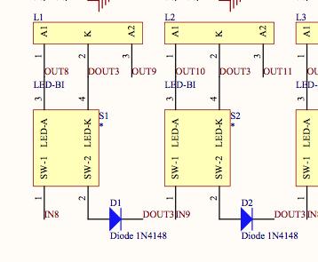
I’ve an assumption: there isn’t a problem with the smaller footprint, but the circuit behaves like if the upper two pins of the button are not connected internally. If you follow the D0 track in the schematic, you will see what I mean: it goes from U2 to GP7, GP5, GP3 and GP1 via the buttons.
(pin 3/4 and 1/2 are connected together), but somehow this isn’t the case at your side…?
You could check if this assumption is true by soldering a short wire at the upper two button pins of all GP buttons (start with GP7, and check if GP5 is working thereafter)
Alright - no problem, this was a nice challenge (something like a text adventure
Desoldering will be extremely time consuming, and there is a higher danger that tracks will be damaged and the circuit won’t work anymore without fixes.
It’s probably easier if you would cut some tracks with a sharp knife, and re-connect them with short wires.
Just a note as i recalled you said the led’s have yet to be installed… Remember led 27 or somewhere around there the polarity is reversed as to the rest of the led’s… Your not careful you can miss it…
Do the ITT D6R fit out of the box?? I first wanted to buy them too cause I like round simple buttons, but was unshure, cause the inner holes of the wilba panel are not 5 by 5.
@ungleichklang: the pins need a little bending before they can be inserted, they won’t sit perfectly flush with the board and you need to take care to align them right before soldering. (i think i soldered one leg first then checked if they sit right and reheated if nececcary)
sorry guys for resurrecting this dead thread, but don’t wanted to make a new one for this.
I was about to build a Seq v4 with wilba frontpanel when I found really fancy buttons from an old video titler. Strange footprint but I don’t mind etching an adapter pcb.
The doubt is: it’s possible to use 2 pin SPST switches also in place of the 1-16 step buttons?
The doubt is: it’s possible to use 2 pin SPST switches also in place of the 1-16 step buttons?
As your SPST switch probably stays in place after the switch operation (like off -> on), this is not practical, as MBSEQ functions are triggered by a short “off->on->off” pulse, when you press (and release) the tactical switch.
Wilba’s frontpanel is able to accept multiple switch footprint sizes, though, no explicit need to use the original recommended ones.
As your SPST switch probably stays in place after the switch operation (like off -> on), this is not practical, as MBSEQ functions are triggered by a short “off->on->off” pulse, when you press (and release) the tactical switch.
nope, are non latching, Normally open momentary tactile switches, kind of the ones of a '80s keyboard such as an AtariST or similar.
What puzzles me is: if switches are supposed to be already connected two pins by two pins, this could be the same as using a 2 pin switch and jumpering the other two on the board? But my head hurts when I look at the schem below .
