Alright, so I have my Core, two SID modules and a DIN and DOUT module finished! Onto the Optimized PSU…without the luxury of a PCB. If anyone can guide me to some information on how to read schematics, I’ll gladly read it. I’ve been googling and asking people to no avail, so I figured I’d ask here.
7809: The pins are just 1, 2, 3, left to right?
Power switch: Smash TV game me an extra one of his! A Salecom T80-R. It looks like one of these http://www.allproducts.com/ee/salecom/06-t80r_print.html I can’t find a datasheet so I don’t understand how each of the 6 leads are wired.
Physical connections: I’m building this on a breadboard. Will the ends of the PSU circuit (marked 14VDC and 5VDC on the schematic) be loose wires? Those should have plugs, like this http://www.avishowtech.com/mbhp/images/c2p.jpg right?
Can more than one wire be stuffed into one plug, or should all the wires come out from the breadboard? I’m referring to the fact that there seem to be 4 to 6 wires coming out of the 5VDC icon, and two from the 14VDC.
Hope this isn’t annoying…I tried to do it myself, but I just don’t know enough!
Also, my C64 power LED has two wires in it. Why does the schematic show 3?
Last question for tonight :P I measured the voltages of my C64 PSU connected to my wall. I got about 5V between the ground and the DC pin, but only 10.5 volts between the two AC pins. I get the same result with two different C64 PSUs. Is this normal?
Switch: Either use google “salecom t80-r” (the second hit is the salecom page with the detailed product description) or your multimeter in continuity (beep) mode. Both ways will work just fine.
Physical connections: Plugs always help. Soldering wires directly to modules is not really the best thing to do in most cases. Makes fixing stuff a lot harder. With crimp connectors you usually just put one lead into one hole.
Two of the pins on the LED are connected to the same thing, so technically it’s just two connections.
10.5V between AC pins is fine - without any load on em, the value will be a bit above the 9V that are specified, this is normal with transformer outputs.
Regarding the plugs you mentioned, those ones from SmashTV you linked to are great. I always order a few extra whenever I order from him so I have some on hand.
Get a crimping tool like http://www.curiousinventor.com/store/product/71. It is *easily* worth the $13. (They also sell crimp pin housings and female crimp pins if you need them, but their selection is more limited than SmashTV’s.) I used to hate making connectors like that, but with the right tool it is a breeze.
I looked at some data sheets for the switch, but it’s still a bit confusing. I’ll try the continuity test when I get home, then look at the sheets more to see if they make more sense.
Crimps & Plugs: if it’s one wire for one plug hole, will I need more than one wire coming out of my PSU breadboard? Should I have multiple wires in one hole, or should I link different holes together on the solder side, so each wire has its own hole? I’ll get a crimping tool asap.
Power SUpply: I thought the AC pins were supposed to be 14V? I think my beige PSU says 14V and my black one says 9V. Oh well, apparently they’re both outputting the right amount.
Where have you guys mounted the 2200 cap at the end of the last SID module? Seems like it would get messy to try to attach it to the same breadboard as the rest of the PSU circuit.
Alright, I reallly need help. My dad and the three friends I have who might be of help can’t figure these out, either.
I found the pairs of leads on the power switch that are continuous. I don’t understand why there are only two power switch symbols on the schematic. The datasheet doesn’t help.
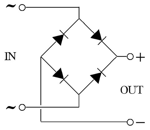
I found the + and - of the bridge rectifier, but I can’t figure out which ~ is which. Does it matter? The datasheet doesn’t help.
I found the pairs of leads on the power switch that are continuous. I don’t understand why there are only two power switch symbols on the schematic. The datasheet doesn’t help.
I think, you mean a double pole power switch. It’s enough for switching on and off two separate secondary voltages as 5VDC and 9VAC simultaneously.
Thanks a lot guys! I’m getting closer and close to understanding this.
My dad explained to me last night how switches are represented in schematics. A lightbulb went off and I realize why I didn’t understand the switch part of it before
About the bridge rectifier, one of my friends explained it to me this way:
If you rotate that image 90 degrees clockwise, you essentially have it oriented how your schematic is.
The negative side is where the two diodes are pointing away from the connection. The positing is where the diodes are pointing towards the connection. Your schematic is labeled, just not obviously so. There is a (+) label beside the rectifier part name, and a (-) label below. Follow those lines back to the rectifier and you have the + and - connections. Or, for the easy answer, look at the diodes on the schematic. The diodes are the things marked like black triangles with a line on top in case you don’t know. There are 4 connections there. Negative is the left one between the diodes. Positive is the right one between the diodes. The ~ connection is on top and bottom.
By this explanation, it seems that the ~ DO matter. Is this particular PSU circuit just an exception?
Meh, I’m sure he’ll be good for something else down the road
I’m already confused again…the schematic shows two writes coming from the plug, labeled “5VDC.” If the ground is not labeled, does that mean it doesn’t matter which wire is coming from the ground and which from that actual +5V line?
By this explanation, it seems that the ~ DO matter. Is this particular PSU circuit just an exception?
If you’d like, I can explain further why the AC terminals of a bridge are not polarized. HOWEVER I suspect that at this point such details will serve to confuse you further instead of help to clarify things.
SO I will stand by my original assessment that they may be swapped without concern, and I’ll offer a friendly invite to discuss it further only if you ask for it.
It is common to draw a full-wave bridge as a square, and everyone seems to have a preference as to how it should be rotated. Fair enough, whatever helps you to see how it works.
To make my point, I’m going to show you a three phase bridge.. one that has three AC legs coming in, instead of the two that you have already seen. As you might guess, it’s no longer a perfect square, but if you look closely, it is THE SAME CIRCUIT.
Now, once you get adjusted to seeing it this way, you’ll realize that ANY TWO of R,S, and T make the exact same bridge you’ve already seen..
So if EACH incoming AC leg could connect to R OR S OR T, what is the difference between them?
No difference at all.
I hope seeing the “different” drawing of the same circuit helps.