Hi,
First of all, I want to thank the Midibox community for such great projects and support!
In the last months I’ve been working building my first MB 6582 and unfortunately I had some strange issues after having it working for some weeks. I’d like to ask for your advise to do a postmortem analysis on what went wrong (more on the postmortem thing later). I decided to go for option B for the power supply, as I want to use both revisions of the SID chips.
When I finished the main PCB I tested all the voltages and everything was fine. Then I tested loading the ICs and with the SID chips and it worked successfully. I was very happy and continued working on the control surface, doing some tests with some new SID chips I got from ebay. To power the MB 6582 I was using an old C64 brick. So far everything was fine.
Then I decided that I should get some other power supply as these old bricks can die any moment, so I contacted Ray Carlsen and ordered one of his power supplies (great power supplies and great guy). Everything was working OK for a couple of weeks, but after that the new power supply stopped working with the MB 6582: the 9V and 12V rails read very low voltages (around 2-3V). Strangely the old C64 power brick continued working properly. This made me think the problem could be on the new power supply, and after many tests I decided to replace the 9V AC transformer myself, always with the help and advise of Carl. Everything was the same. One day, using the old C64 brick the SIDs were not working and I measured the 9V and 12V rails and they were low voltage too… If I switched the MB 6582 off and on again, most of the times it would work again properly.
After that, it was clear that the problem was on the MB 6582, so I started measuring voltages in many places and discovered that the input voltage of the first voltage regulator was around 18V when using the new power supply, and 16V when using the old C64 brick! This was a very bad sign, but it also explained why the one power supply would work and the other won’t: the regulator was operating under too much stress and this 2V difference would make it shutdown. Now being on the right track, I decided to replace the electrolytic capacitors and discovered that one had some dark marks on its side.
When firing it again I started measuring voltages and thinks looked better, but I accidentally slipped one of the probes and made a shortcut in the voltage regulator pins  This blew the fuse in the new power supply, but the 5V part is also protected with a relay, so the power supply survived. Unfortunately I noticed that the other 2200uF electrolytic had dark marks on it. Then I decided to replace all the components on the power circuit, from the bridge rectifier to the capacitors that are after the voltage regulator. Unfortunately my desoldering skills are not very good and when I finished I created a new problem.
Now the voltage regulator has a low input around 4V. The bridge rectifier reads close to 9V on its output, but the negative pin relative to common reads -4V. I checked for AC voltage between the outputs of the voltage regulator and it reads around 4.5V AC
Then I replaced the bridge rectifier again, and that made quite obvious that I had damaged the PCB contacts, as now I have some exposed copper areas around the pins of the bridge. So it’s quite obvious that I have created a short in the PCB (this is why I said postmortem) and I should build a new one once the PCBs are available at the midibox shop.
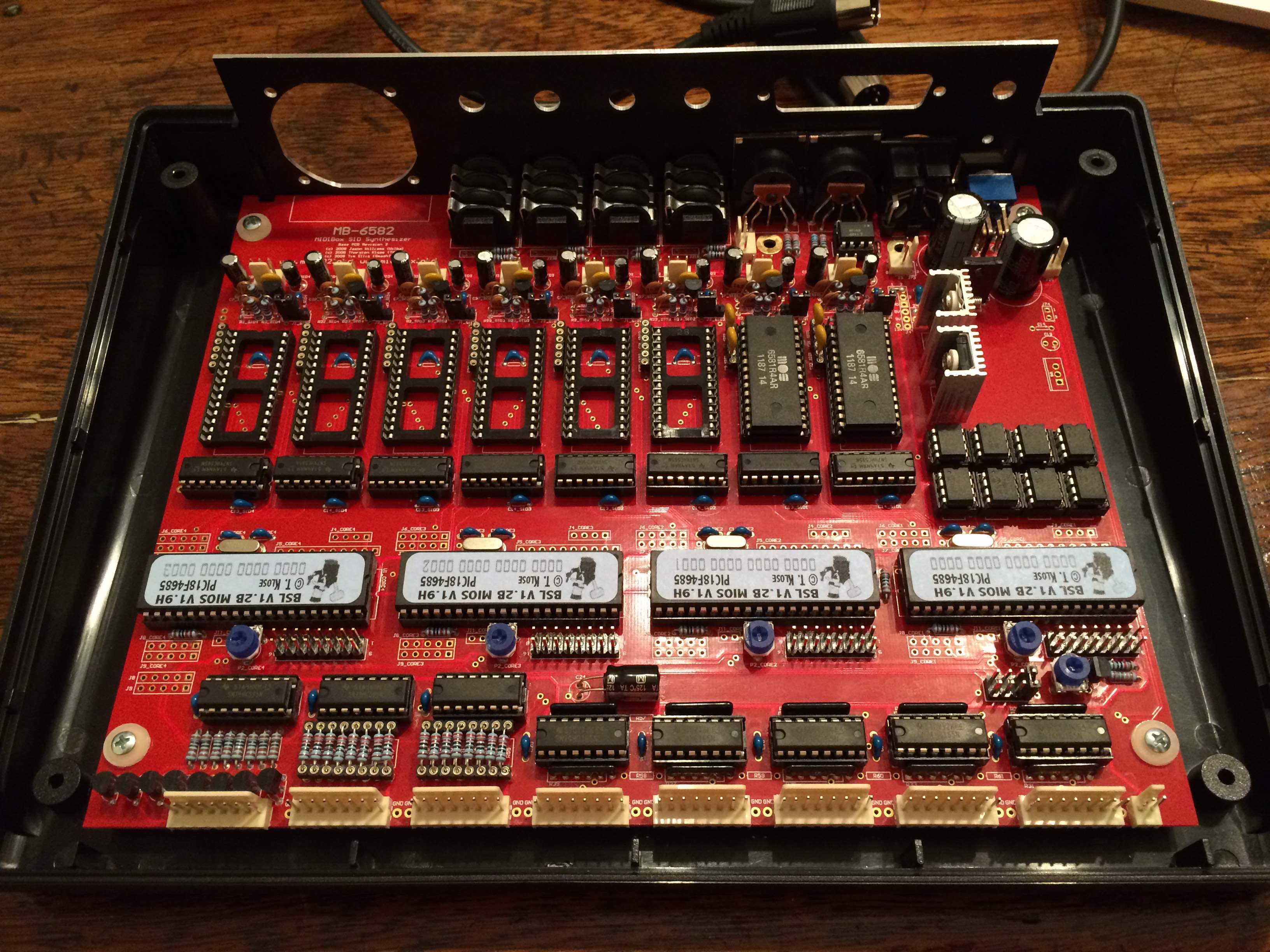
My first diagnosis was that it could be that I placed one of the big electrolytics reversed, but I have a picture of the board when it was working OK and they seem to be in the right position (see attached picture). I’ll build a new board from scratch, but I’m still wondering what went wrong and how to avoid it happening again. Any advise or checks would be more than welcome.
Thanks a lot and sorry for the long post. Cheers!