On 5/23/2019 at 6:22 PM, rbv2 said:
hi all,
after testing i found an minor issue with my breakout-box. everything is working as intended but i get annoying double triggers on some modules. when i connect the same modules to my robokop sequencer or other trigger source everything is fine. could it be a grounding issue?
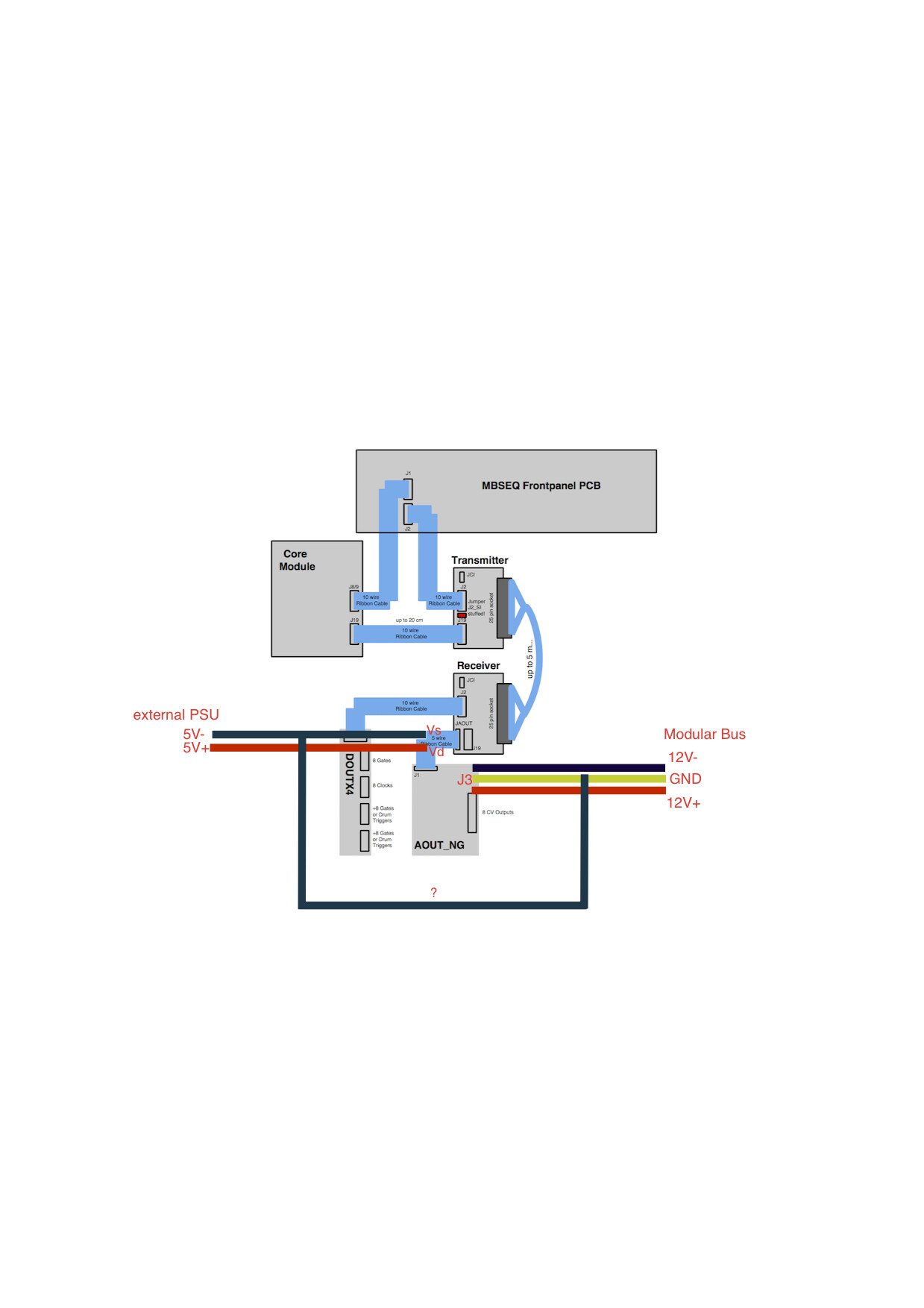
the +/-12V for the AOUT NG is coming from my eurorack and the +5V for AOUT NG and the LineDriver Receiver from an additional psu. the external psu (5v) is in the middle of the ribbon cable between AOUT NG and the receiver as suggested by latigid on. i also enabled the 1ms trigger but it makes no difference.
when using the same trigger on another module it works so i guess i can rule out the double trigger is coming from the sequencer itself.
please help
rbv2
I repeat my advice from the other thread:
Could it be the HW config settings or an issue with midi loops feeding back in? More than one track assigned to AOUT?
The perennial IDC cabling issue would also be worth checking.
You could also test with _NG again and in MIOS terminal
set dout x 1
to check if the problem is replicated. For x you have to count the number of shift register outputss in the chain, starting from 0-7 for the first one. Or simply replace x with ‘all’.
21 hours ago, Hawkeye said:
Therefore, I would also expect maybe a common ground problem on your side? Have you grounded the external PSU and the LineDriver Receiver to the modular/rack common ground?
Check the resistance of your 0V from the Eurorack to somewhere on the SEQ e.g. pin 2 on a MIDI out (the one at 6 o’clock).
In the line receiver, is jumper J3 closed? This could cause interference on the +5V line if there are two PSUs fighting.
12 hours ago, rbv2 said:
at the moment i have wired 12V+/- and GND directly from a doepfer bus board to J3 of the AOUT NG the external psu is in the middle of the cable from JAOUT of the receiver to J1 of the AOUT NG. (Vs & Vd) . by common ground do you mean i should connect the Vs line of 5V PSU to the GND of J3 at the AOUT NG? all the jacks (gate, trigger, cv) are connected to ground and since the panel is made of aluminium the gnd of both psu’s is connected.
If you use an external PSU you must connect the 0V together with the +/-12V PSU 0V common line. A metal panel is not a good (and some would say unsafe) method of achieving common 0V.
12 hours ago, rbv2 said:
i have also learned that the 5v on the doepfer boards are not there at all although it is written on it
I guess you are not using the +5V on the bussboard? But if you are, maybe you don’t have +5V connected and the modules are being parasitically powered from the digital signals? (This is not good for CMOS btw.) Did you measure correct +5V on the modules?
9 hours ago, Hawkeye said:
Probably can help you out way more than i can… but i just looked up the AOUT_NG schem and it seems analog ground can be tied to digital ground (see middle of the schem), maybe by a jumper? If that is the case, i think the grounds should be all tied down together and nothing is floating, which might cause problems. We are using the AOUT (not NG) module, so i don’t really know much about the NG.
There is only one “ground” and the separation of analogue/digital 0V is a complex and often misunderstood topic. On AOUT_NG the two are connected underneath the DAC chip; there is no jumper etc.
9 hours ago, rbv2 said:
a friend of mine will lend me his scope. but i don’t have one right now.
A scope might be useful to see what’s going on.