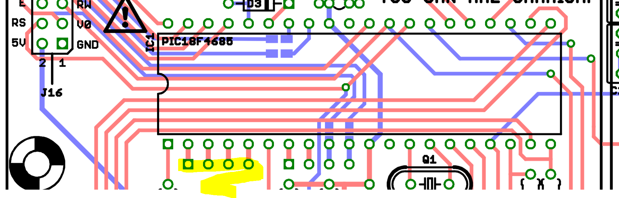
If you look at the Base PCB, they were kind enough to break out the ADC pins:
:
You have to enable the AINs by compiling new SID firmware:
http://www.ucapps.de/midibox_sid_manual_fp.html
Quote
Analog Control Elements
With MIDIbox SID V2, analog control elements like pots, faders and joysticks are natively supported. Everything you can find in the forum about such an extension for V1 is obsolete, especially because a dedicated driver is used instead of MIOS_AIN for optimized performance.
This feature has to be explicitely enabled within the setup_*.asm file by setting DEFAULT_J5_FUNCTION to 1 - once you did this, all unusued analog inputs must be clamped to ground in order to prevent random values! This is especially required for the slave modules, when the master firmware will be transfered to the slaves via ECAN (clone feature).
All 8 analog inputs are sampled with a frequency of 125 Hz. Multiplexing (-> MBHP_AIN module) is *not* supported! So, 8 inputs are maximum.
The firmware currently only uses the first 5 inputs of J5, the remaining 3 are reserved for future features.
The converted values are forwarded to the knob handler. This generic approach gives you all advantages of the knob concept: value changes can be forwarded to two sound parameters, a Min/Max range can be specified, and the converted values are also available as modulation source!
The feature behaves differently on master and slaves:
- Master: analog inputs are forwarded to the *selected* SIDs. This has the advantage, that each SID can be controlled from a single set of pots and/or joysticks. If you find this impractical, a small and harmless firmware patch (AIN_NotifyChange: remove the branch to “AIN_NotifyChange_Master”) allows you to realize a dedicated control for the master only.
- Slave: analog inputs are only handled internally independent from the selection.
Note that this feature can also be used to control the SID from analog signal sources, e.g. from an analog step sequencer, or an analog LFO.
take special note that unused inputs must be connected to ground. So if you used the first 4, clamp the 5th. I’ve got no idea if anything will be different for the sammich variant, as some of the pins are evidently supplying data to the LCD.
I take it you want actual CV rather than pots, so you should use clamping diodes or a rail to rail op amp limiter to protect the PIC from over/undervoltages.