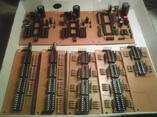
update: now all PCBs from Mike’s are soldered: 1x CORE, 2x SID, 2x DOUTX4 with the bridges for modulation matrix and 2x DINX4 + 1x DINX2 for step C ctrl surface.
i just learnt that i don’t need the rectifier / vreg circuit on the core pcb when using the original C64 psu. so i’m thinking again about using trafos for each voltage, depends on finding some quite fast…
2 important questions for today:
a) i’ve searched everywhere in forum/wiki/uCapps for a description of the transistor driver circuit for the LEDs in the modulation matrix, but haven’t found anything… does anyone know where to find information about that?
b) would the use of low current LEDs in the MM require change in resistor value (220ohms)?
thanks!