Hi there im new around here.. ! I have bin looking at this MB project for a few years and now final started on a MBSIDv2 minimum stereo setup. i have some trouble with the optimized PSU.. i will try to explain my self.. im kinda new to electronics but i find it very exciting and i like to read and learn.. i hope some of you can help me out here.. as im a little lost.. :-[
I think this might be a problem with the components I chose to build this circuit..
here is my part list:
KBP208 bridge instead of the B40C800
L78S09CV instead of the 7809 voltage regulator
2x 2200uF 50v instead of the 2200uf/25v and 16v
u1K63 instead of the 100nf
u33K63 instead of the 330nf
then im using the original power switch from an C64-II
the power plug connector and the psu from this C64-II
My trouble is that this not working .. :///
Im kinda noobish in all this but i’ve made some multimetering and this is my result
so… i’ve checked the circuit many times for any shorts or mis-wire-ring but this does not seem to be the problem.. so my mind is on wrong components..
well any thoughts and guides to were i go from here is very welcome… and i hope this makes any sens at all..
It looks to me like your components selections are good. I’m guessing the L78S09CV is bad, or something around there.
Where is the vertical wire in the schematic that goes from the right of the base of the 7809 (pin 2) down to the 5V section? I don’t see a wire for that in the picture of your board.
thank you very much kurt.. you have great eyes for spotting that one.. and it seems to work.. (the vertical wire was missing. !!)
and then not really.. i now get around only 5vDC from the 3pin of the voltage regulator..
can this be a crazy chose of component? - and then im still confused about the low AC voltage in the circuit before it hits the voltage regulator..? is it normal that this old PSU is acting random voltage on the 9vAC output?
and thanks for a quick reply.. next time i will go over the circuit even :0(
this might be my bridge that is broken or wrong-wired.. the vDC on the bridge -/+ output gives me 0.56vDC just under one volt.?= thats not good… (this i with the strange random right now at 5vAC input on the two ~~) and across pin 2 and 3 on the regulator then gives me the 0.0vDC
strangely enough my bridge outputs about 5vAC… here is how i have wired it.
?¯¯¯¯¯¯¯¯¯¯¯|
| KBP208 |
| + AC - |
| |
¯//¯//¯¯¯\¯\ <- the two outer legs is output right?
* *
* *
* * <- 9vAC output connected here from the C64-II psu
I would disconnect any wires from the + and - on the bridge before declaring it dead. Sometimes other failures can make strange things happen there. But I can’t see any reason why you would ever measure any significant amount of AC on the output of the bridge. Measuring the DC voltage across the + and - pins of the bridge when it has no other connections made to those pins should help you confirm whether it is malfunctioning or not.
I’m not too familiar with the inner wiring of the DIN socket that you are connecting power to, but make sure that you are connected to the correct pins there for sure.
Try to measure the voltages at your C64’s PSU plug. These things are quite old and some of them are faulty. Measure the voltages on the PSU’s power plug. It should be +5VDC on pins 3 and 4 (counting clockwise) and ~10-11VAC on pins 1 and 7.
yeah thats a good idea, i that from the start aswell. the multimeter gives 8-9vAC on the pin 1 and 7… and then i get the 5vDC on the 3 and 4 pin.
i switch to checking every thing now before i mount it… so i basicly started all over..(i guess it was abit naive to solder every thing up and hope for the best)
i have a fine connection thru the switch and then i connect it to the bridge. 8-9vAC connected to the bridge i get 1.59vDC out the bridge(i tried the bridge i pulled off my circuit and a brand new one and its the same 1.59vDC on both).
is the 8-9vAC too low for my psu?
and whats up with my bridge? am i getting the right result in DC voltage output?
Measuring voltages on unloaded PSU is one thing, on loaded - another. Try to connect another PSU (wallwart or whatever you have with similar voltage) to your circuit and measure the voltages after the bridge and avter voltage regulator. Good luck!
ok thanks alot zgba, this cleared out a few things..
i fund one power supply at with the output specs like this: 9vAC ~ 1.1A 9.9VA
what is that [9.9VA]? - but any how.. i measure the output to be 11.1vAC and i connected it to the bridge witch gave me 9.74vDC output.
so i guess my c64 psu is crap.. if i were to make a it work just for now, could i then go for a two psu connected? one being the old c64 psu for the 5vDC and the other new one for the 9vAC? - and then build the same circuit?
Using 2 PSUs is rather inconvenient. You can do it temporarily, but you should avoid it in your final design. But don’t worry you have number of solutions: you can buy another C64 PSU on eBay or something like that really dirt cheap and re-use it without modifications or you can use this 9V PSU you have for +9V and +5V, but then you have to design another PSU and use some heatsinks for 7805 regulator. There are appropriate schematics somewhere in the forum, in the midibox FM section I think.
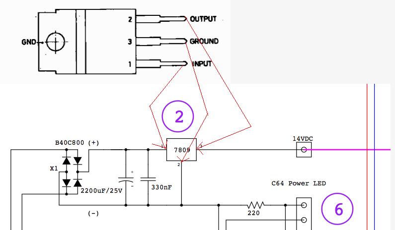
im a little confused here.. i look at the datasheet for my L78S09CV voltage regulator, and how the 1,2,3 pins is set and it looks like pin 3 is ground and on the optimized psu circuit pin 3 is the 14vDC output? can any one help me about how to connect my voltage regulator? im way to noobish to make the decision that i should move away from what the circuit tells me or what so ever.. :0)
 I have bin looking at this MB project for a few years and now final started on a MBSIDv2 minimum stereo setup. i have some trouble with the optimized PSU.. i will try to explain my self.. im kinda new to electronics but i find it very exciting and i like to read and learn.. i hope some of you can help me out here.. as im a little lost.. :-[