I’ve decided to go ahead with my midibox64 project.
I’m planning a design with
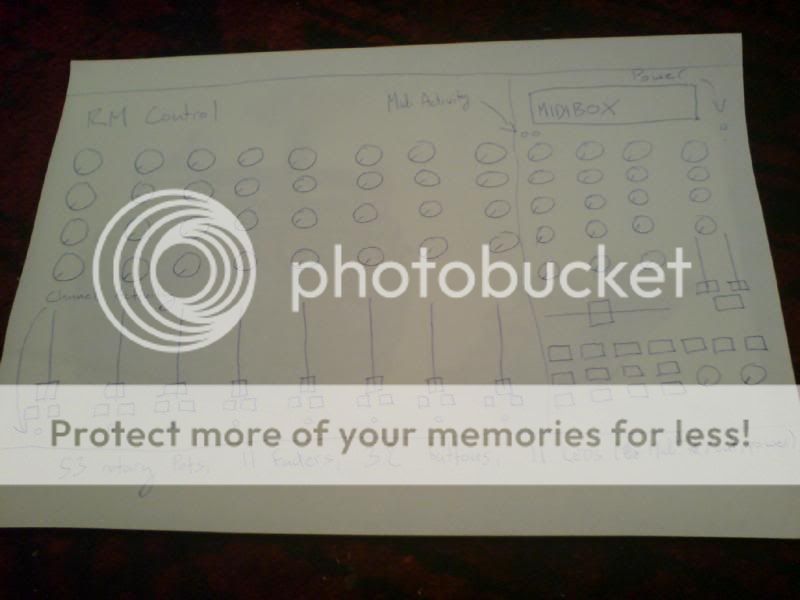
53 rotary knobs
11 faders
32 buttons
11 Leds
and an LCD!
The plan is to use
1 Core - PIC18F452 (Kit from Mike’s)
2 AINs (Kit from Mike’s)
1 DIN (Kit from Mike’s)
1 DOUT (Kit from Mike’s)
Plus:
LCD 16x2
LED, red 3 mm
from Mikes
11 faders
53 rotary knobs
32 buttons
(from RS).
I want to build the device on breadboard and then transfer into a box when it works!!
Is using 11 LEDs on a DOUT going to lead to issues?
also, is using only 1 DOUT and DIN going to cause problems?
if any one has any ideas, help or anything get in touch!
heres a photo of a very rough layout!
Cheers
cimo
January 19, 2008, 1:19pm
2
Is using 11 LEDs on a DOUT going to lead to issues?
also, is using only 1 DOUT and DIN going to cause problems?
no & no
simone (who the f*ck is cimo?)
Is using 11 LEDs on a DOUT going to lead to issues?
It looks to me, that you’re driving 10LEDs from the DOUT. - It makes more sense to hook the Power-LED to the 5V side of the PSU.
Greets, Roger
dj3nk
January 21, 2008, 3:44pm
4
It looks to m e like 8 Leds. 2 are for midi in /out. They should be connected to a ltc. Power led like screaming rabbit said
It looks to m e like 8 Leds. 2 are for midi in /out. They should be connected to a ltc. Power led like screaming rabbit said
:P… äääähm, yepp. :-X
Thanks for the correction of the correction
Greets, Roger
cimo
January 21, 2008, 4:47pm
6
from main.asm
; For MIDI activity monitor: define the DOUT pins for the Rx and Tx LED

#define DEFAULT_MIDI_MONITOR_ENABLED 1  ; if 1, the Tx/Rx LEDs are enabled

#define DEFAULT_MIDI_RX_LED 0x40	; DOUT SR#9, pin D0

#define DEFAULT_MIDI_TX_LED 0x41	; DOUT SR#9, pin D1
simone
dj3nk
January 21, 2008, 6:28pm
7
recorrection of the corrected correction.