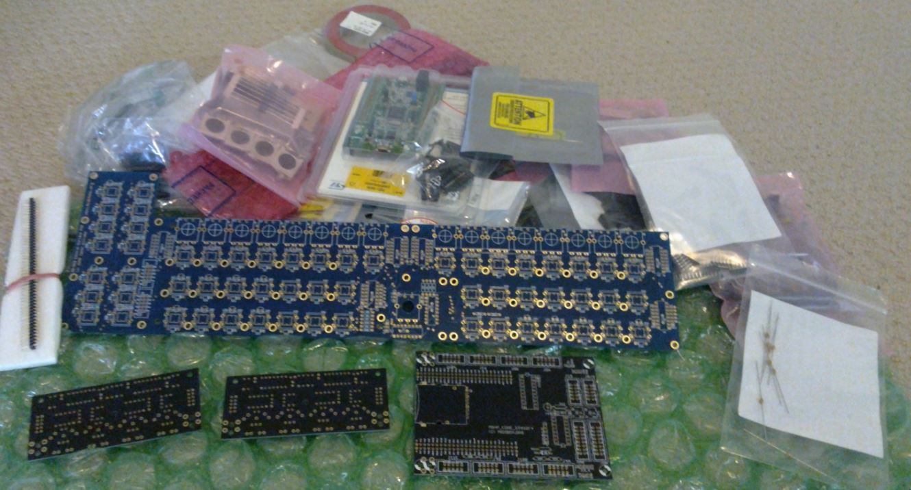
Inspired by Hawkeye I thought I’d document and photograph my MidiSEQv4 build in the hope that it helps others.
I’m planning a fairly vanilla SEQv4 with Wilba’s CS and 2 MIDI IO boards. I’ll add the Raystar OLED displays instead of LCD. I intend to build a Ponoko acyrlic enclosure and will publish the SVG for once done.. I’ll edit this post as I go.
#0 - BOM and Excitement #1 - - Storage for baby voles #2 - - Trust datasheets #3 - - Chill to the bood #4 - - Time is neither created or destroyed. Merely borrowed and given back. #5, #6 - - Fat Tabs #7 - - Alps Encoder Edition #8 - - Aaah #9 - - Dun dundun dundun
NOTE: This is not a build guide. It is a documented summary of my attempt to build a SEQv4. Some parts from the BOM below may, and indeed already have, changed as the journey continues.
Full BOM Summary
I’m in Australia where the AUD makes this quite expensive. I’ll include costs in AUD and the original currency.
Yes Mongrol go for it! I’m awaiting the same shipment from Smash TV and I’ll most probably order all other parts from Mouser. There must be some acrylic case designs lying around somewhere in the forum.
There must be some acrylic case designs lying around somewhere in the forum.
The most standard laser cut template I believe is from smokestack. It has bugs though and hasn’t been updated. I’ll be making a new one with interlocking slots round the back and sides with the only front edges using the “teeth” method. It’ll be optimised for size as much as possible without modifying the boards beyond vanilla.
Yeah, I did at one point switch back to the 16mm ALPS to be more vanilla but once I seen the price ($75 for 17) I went back to the 12mm ($37). Mouser may say free shipping but they mark it into the price.
When using the ALPS 12mm encoders, make sure you cross the center and the right pin (as seen from above). It takes about one minute per encoder and is the correct way of attaching them. You can live with DETENTED1 probably, without this mod, but it is best to do it correctly (for more info, see last posting in the phototutorial thread)
The most standard laser cut template I believe is from smokestack. It has bugs though and hasn’t been updated. I’ll be making a new one with interlocking slots round the back and sides with the only front edges using the “teeth” method. It’ll be optimised for size as much as possible without modifying the boards beyond vanilla.
That sounds just like what i am trying to come up with. If you’d share your files once you’re done, that’d be great
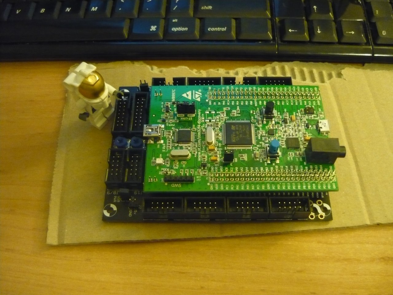
Next I installed the bootloader. Reading the instructions isn’t totally clear but I figured out I needed something to connect to the STLinkv2 debug program on the board. Being on linux I opted for QStlink2 on Github. This cloned and compiled no problem on my Debian Jessie box once I installed some lib-devs. You have to install some udev rules to run it under a normal user. Once done it detected the Core and I could upload the bootloader. It worked flawlessly and much less hassle than trying to get a Virtualbox up and running with Windows on it.
MIOS32
I hit a bug in MIOS32 trying to upload the SEQ project.hex file. This had a workaround.
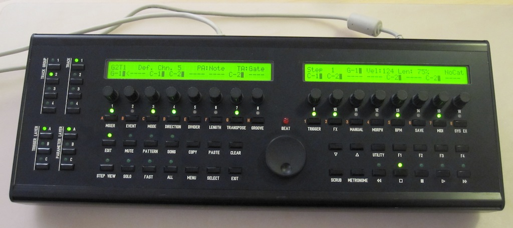
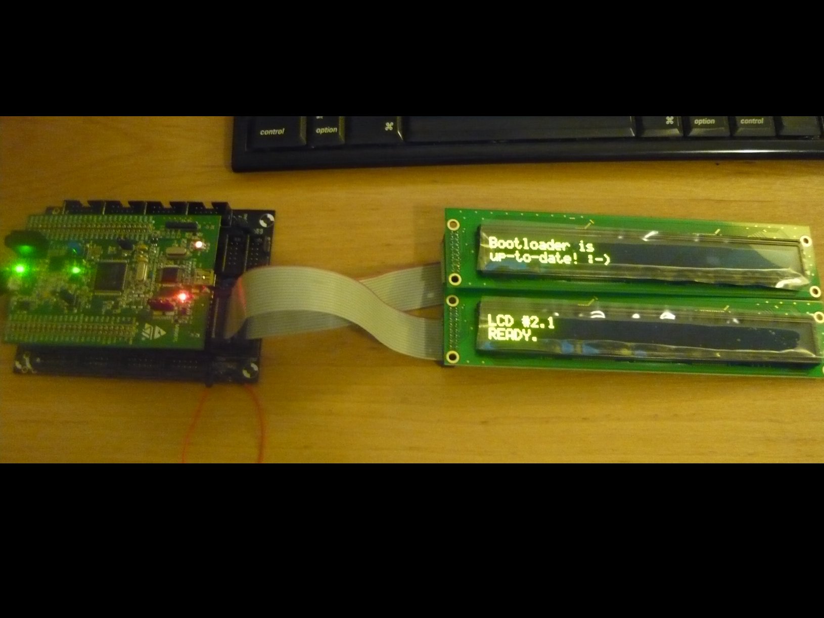
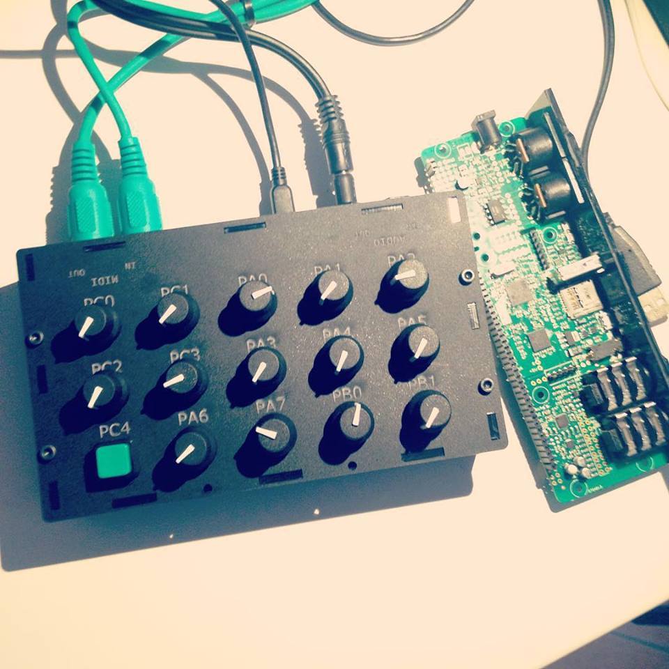
SEQv4 application uploaded and appears ok. Hmmm, next up, MIDIIO or displays? DISPLAYS!!! I have to see things ON!
Well that was both easy and hard. Making IDC cables is very easy. Simple cut the cable with scissors and, making sure you align the striped bit with the little triangle on the plug, poke it through the jaws till it’s flush with the other side. Then squeeze it together. Make sure you do it evenly (a vice is good) as if you don’t you may snap the side clips. So use a big set of pliers or something you can get even force. Then fold the cable over the top nice and tight and push on top locking thingy.
I made cables up and looked at the pinout on the OLED. Pin 1 was nearest to me so I put the cable on with the stripe at pin one. Plugged it into the Core and nothing. Hmm, stared and poked, replugged, stared at solder joints. Tested with meter and got funny readings. Then found a post about 3.3v and set lcd_type 0x02. I started playing around with that and managed to get one display up. No luck on the other. After hours of staring, poking, reflowing joints, reading schematics and testing I discovered the 5v OLED’s should really be 5v after all. Who…would…have…thought?
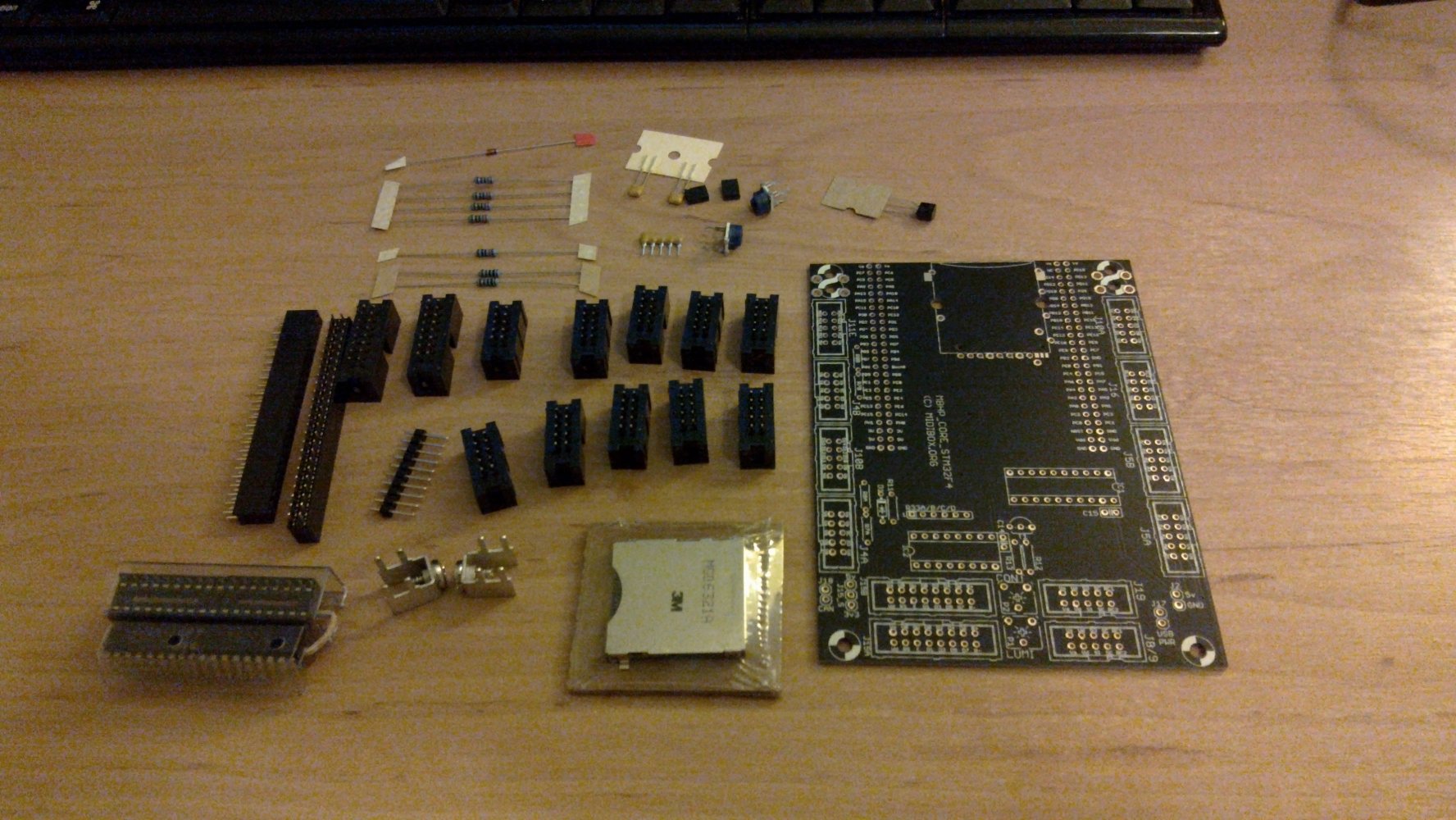
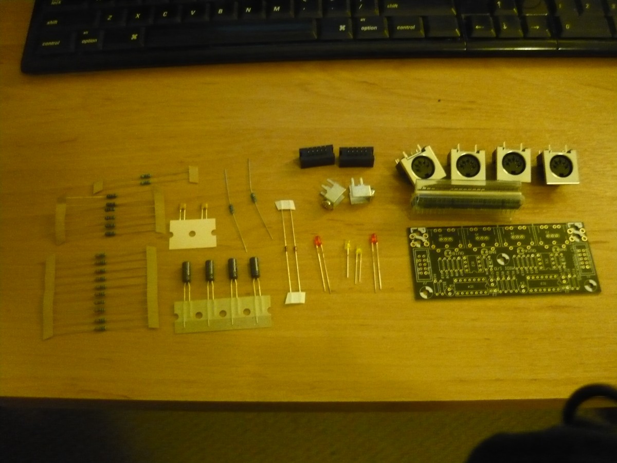
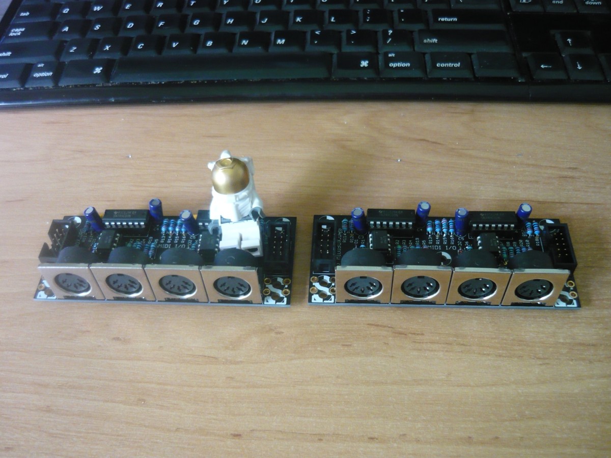
So easy I didn’t even use a Hawkeye visual aid. The ucapps midiio page has all the placement information in it. One thing I will point out is the order is wrong. Do the IC sockets and headers before the big caps (height order y’know) then finally the MIDI sockets.
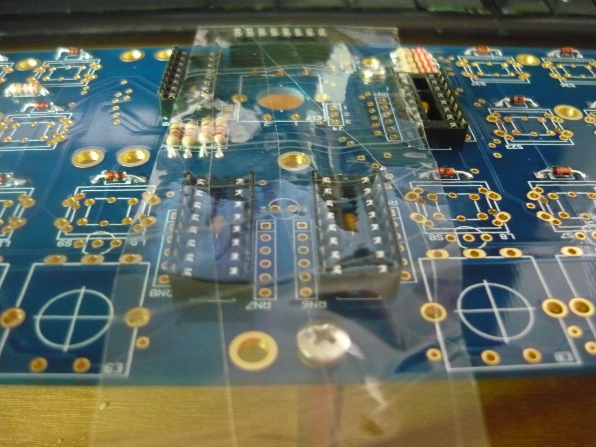
The CS seemed a bit daunting at first until I found out about “top soldering”. The CS is double sided with pads on both sides meaning you can solder on either side and get good joints. I took advantage of this wherever I could. Amazing speed up.
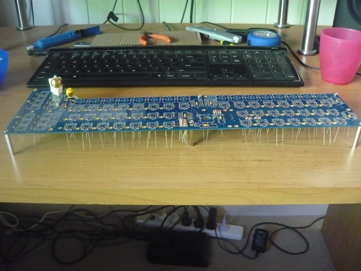
First we put the board up on standoffs high enough to let the wires of the components dangle without touching underneath. Following I dropped the diodes, resistors and caps in one go then soldered them all up, turned it over and snipped all the tails off. Top soldering is a magical time machine! The joints look nice and clean and it also makes for a lovely neat underside.
Unfortunately that’s where it stops. The IC sockets can’t be top soldered so I used the tape method instead. If you don’t want to use tape I sometimes use a bit of cardboard to cover them and hold them in place while I turn the board over. Same result.
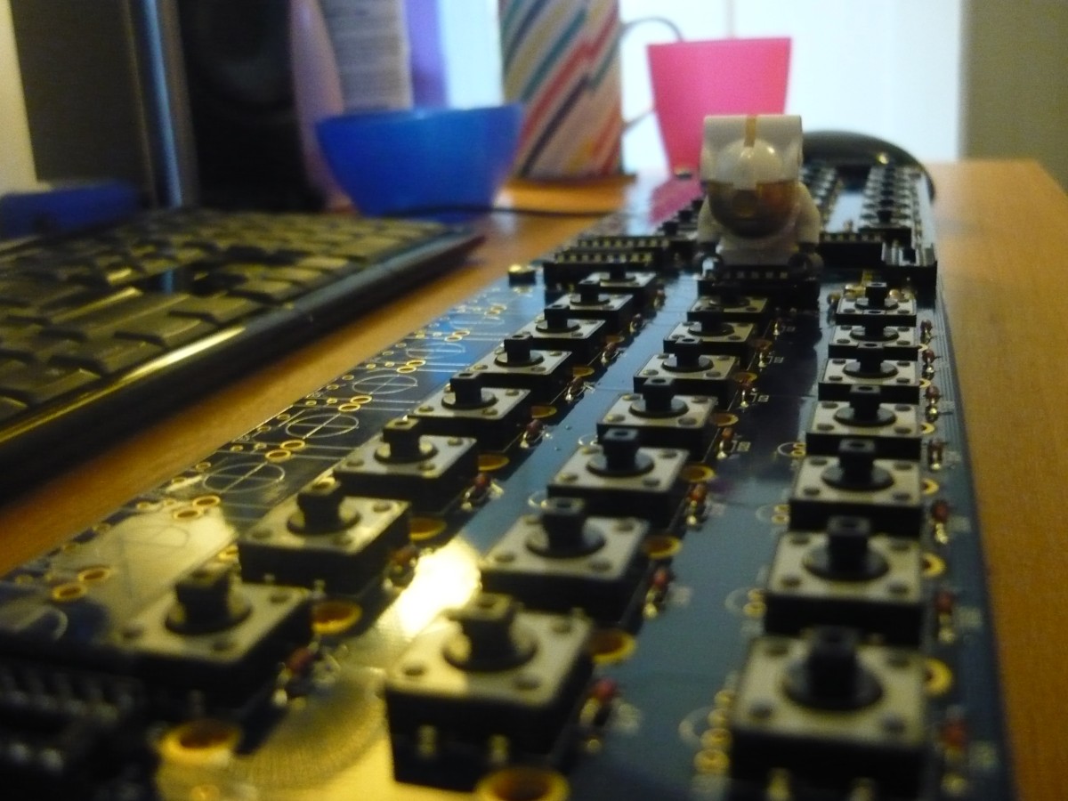
After that we’re onto the switches. They all click in nicely and stay in place when you turn the board over. 232 joints later and we’re nearly done.
But disaster striketh the mong! Alas I’m stuck! My boat has been cast upon rocks. I’ve been foiled by incompetence (probably my own). The box connector needed to talk to the Core is a 10 pin SMD part. I’ve been sent the wrong thing!!!
Well that answers the question I had when I first went through my delivery. I now await the opening of a local and dusty electronics store before I can move on.
Alas I’m struck down. I can’t for the life of my work out the orientation and wiring for the IDC ribbon to the Core.
I was trying to do an angled IDC box header underneath but no matter how I make the cable or which ever way I put the box header in I always end up with the wrong pins.
I assuming S0 goes to S1, Rc goes to Rc etc? But I always end up with either S0 to S0 and Rc to Rc or S0 to S1 but with Rc going to VS instead.
It’s a straight connection. So just make sure that you have Pin 1 (red wire) coming from the Core on J8 to CS J1 go to Vs.
Yes! If you are missing that one connector and just can’t wait to “fire her up”, you can always solder in the required wires directly on the CS board (and add an IDC plug on the other end of the ribbon wire for the core, so you can still disconnect things). You can measure with a multimeter in connectivity/beeper mode from the core and solder in the wires on the appropriate pins of the cs… This should be done in a few minutes…
Should be mentioned that the ribbon connection is made on the underside of the SEQ PCB. Also that you don’t HAVE to use a box header, regular 100mil pin headers are just fine. When looking at the IDC connector from a bird’s eye view, the notch goes at the bottom and pin 1 is the lower left. Just match the left sides together as Shuriken says and you’re golden.
(BTW it’s SI and SO, for serial input and output. SO from the Core drives the DOUT chain, while SI to the Core carries the DIN data stream.)
Thanks Guys. I ran out of IDC connectors (they don’t survive 10 removals) so have ordered more. I’m happy enough to leave testing until they arrive. I have one encoder soldered up so will now move onto the enclosure.
With all my switches on and 1 pot (and waiting on parts) I might as well get on with the enclosure.
Lots of people like to use the tooth method for acrylic boxes made either manually or with Boxmaker.
Boxmaker’s pattern looks far too aggressive for me, I bet it grips on like a ugly steel bear.
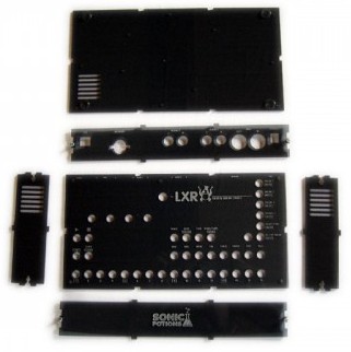
Others use the same method but reduce the tooth count to make it nicer. This works to a certain degree but reduces the stability and solidness of the casing. I had one of these around my LXR for a time. It was ok as I don’t gig but it wouldn’t last long.
All of these teeth designs use “key” screws in the sides to keep them together. Without them the side’s would be pushed apart by the pressure from the top and bottom panels which are screwed together.
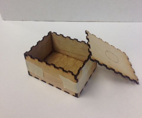
On the Axoloti forum I found this design. The teeth go inside slots in the top and bottom panels which are screwed together. If the teeth and slots are accurate enough (kerf accurate) then you don’t need key screws in the sides. It also has nice rounded corners. I like this a lot and will attempt it with my SEQ.
I’m also going to attempt a couple of other improvements
The only screws that show in the top panel will be the ones around the side holding the top and bottom panels together. The CS will be standoff’d to the bottom panel instead of the top to avoid any middle of the panel screws showing. To stop panel flex the CS will have 10mm standoffs on top holding up the panel. You just won’t see them but they will be there making everything sturdy.
I’m going to reduce the size by using the CS mounting holes (and 1 Display hole) for the case edge standoffs that hold the case together. The CS will be 1-2mm away from the case edges with no standalone standoffs around the side.
The display holes are a bit tricky to bottom mount but we’ll see how we go.
I hate the thickness of the core. Would love to decimate that audio socket badly but that would mean making a non-standard case that others can’t use.