at RGB-Leds > i dont know, how many you will use? which coremodule you will use? is it eurorackbased > and eurorack powerd? Which RGB-LED you will use - and what is the Voltage it needs? and so on…
i looked into your files… some notices:
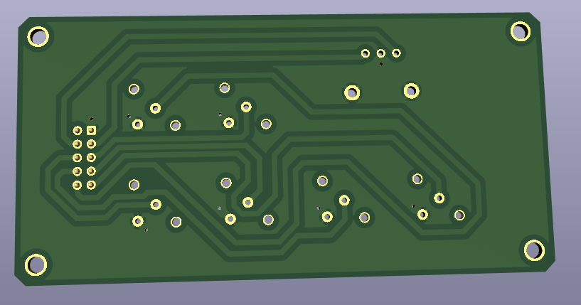
@BP:
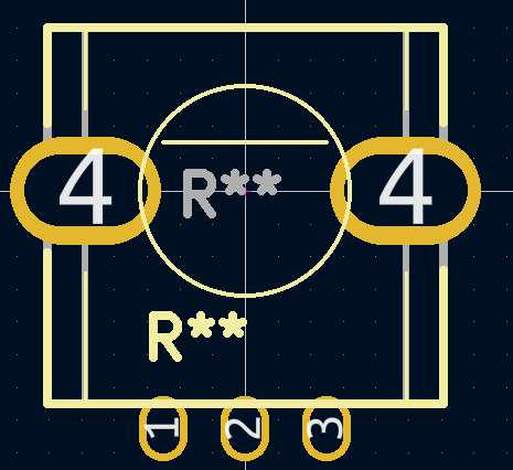
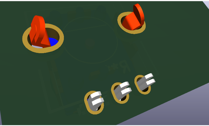
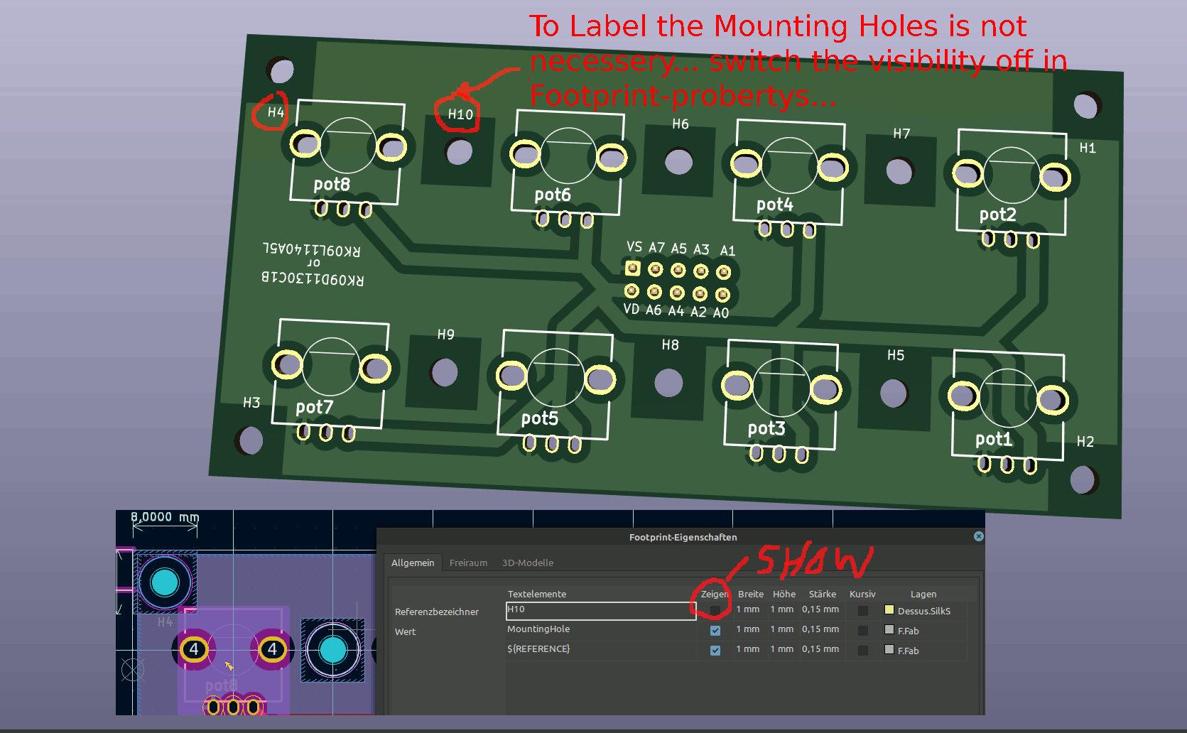
dont connect the mountingholes to ground, or any other potential, best would be to make a keep out-area (sperrfläche) arround it, like i did for example here: http://wiki.midibox.org/lib/exe/fetch.php?w=600&tok=f96292&media=phatline:daw-btn-3d-b.jpg
since you can plastic and/or metall standoffs to mount that pcb to the panel, you would need at least 6mm or more keepout-area…
background: you want to avoid groundloops over the frontpanel, and the risk of a electrical shock is less…
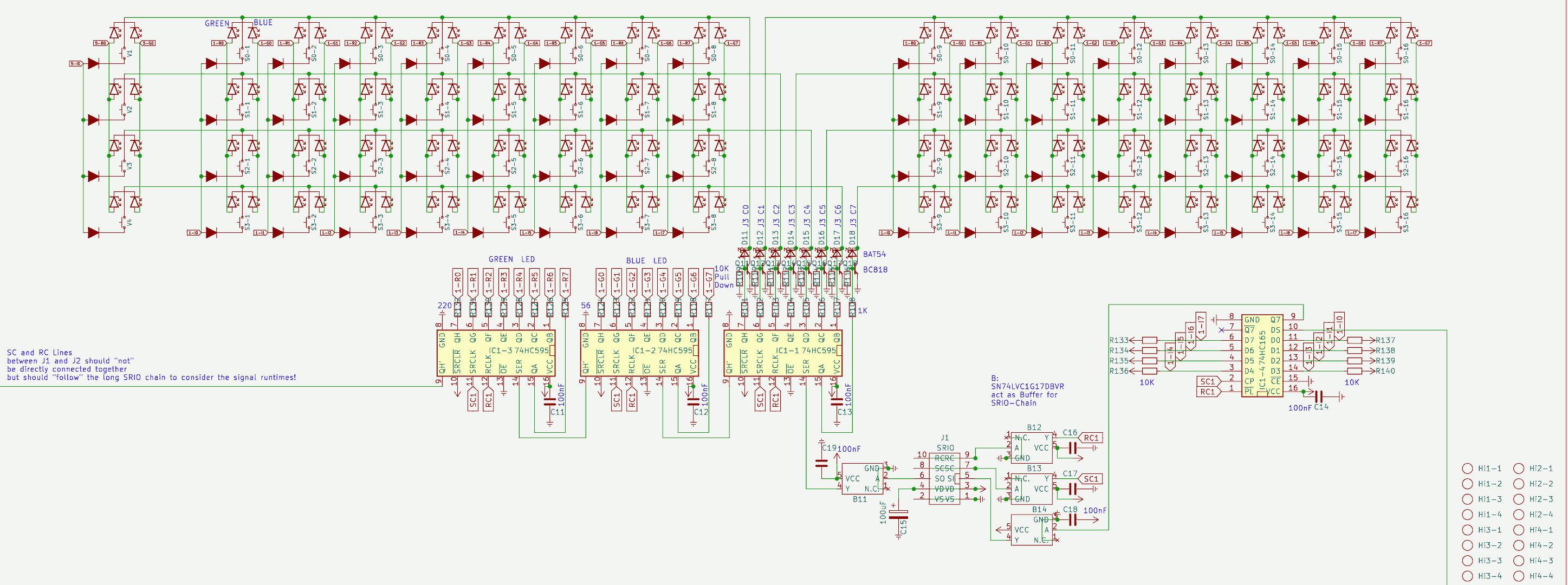
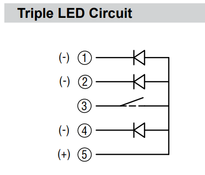
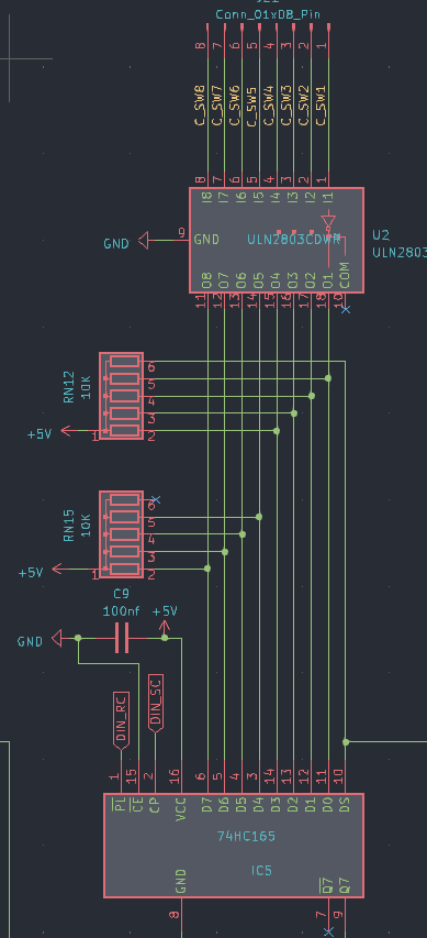
The LEDs in the diagram are connected false, the tip off the arrow should always be connected to the ground. (you should turn them 180°)
which buttons do you want to use? please check the pinout off them… for me it happend that i did not connect the correct pins, so double check this…
why you made those cuts on the 4 corners? its better to make them rectangular - background: if you panelize the pcb, you have to draw a V-Grove line, the machine can only Grove in 90°, the idea, is to put 2 off this boards on one 100x100 PCB so you can save money on FAB…
way more oversight you have if you use a Groundsymbol… instead off paint Lines to a ground inside your shematic… look into “control” to see what i mean…also it makes it easyier to work with groundplanes, since this needs a NET…
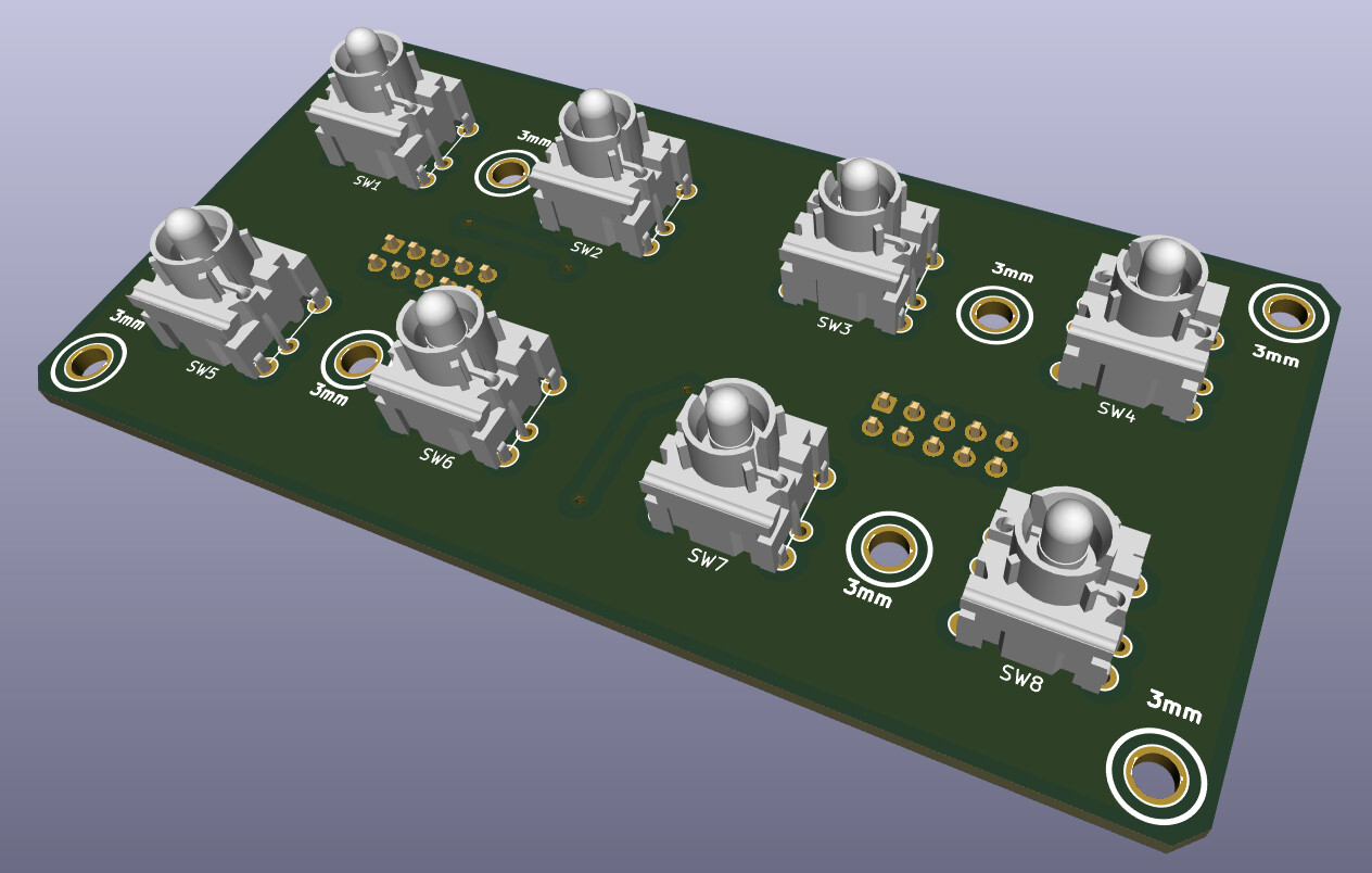
@Control:
please open this file:[Control.zip](< base_url >/applications/core/interface/file/attachment.php?id=15930&key=20132689c91f71d1c16cc6dc1a2a2344)
the same like above, and, you dont need that vias next to PIN 2 off the switches > Pin 2 is a via itself… - same for Pin 1 off P2, the Problem it did not fill without your Vias: because you dont used a Ground-Net…
Pin1 - which is labeld as VDD (+) was connect to all your buttons and the pot (which is a Encoder)… normaly we connect them to ground…
VSS is ground… so i exchanged the whole thing… i dont know iff this is then still correct in your big picture- wiring diagram… how ever thats the way i would make it - at least iff the Pin-Labels off the IDC Connectors are right…
you should put the 4 mounting holes in the shematic, so you dont loose them when updating the PCB
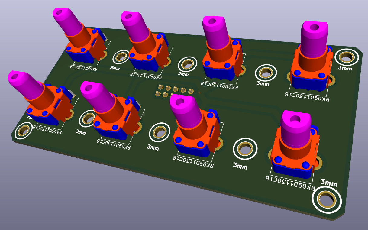
Also dont label your Encoder with Pot or RV >>> this is not a Potentiometer… that confused me until i realized this is a Encoder…
also the google-Drive files are a bit corrupt - the footprints where not assigned to the Shematic symbols… when you save the project and upload it somewhere - zip it inside Kicad with “Projektdaten archivieren” - dont know the french word for it.
-please overwork also your BP like/or simular like i did…
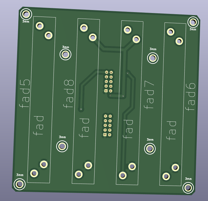
@Fader 1/2… please open this file: [Fad_2.zip](< base_url >/applications/core/interface/file/attachment.php?id=15931&key=ace388736f63f83dbc2ebb61c58b993b)
shematic: also better use GND and VDD Nets… more oversight! if you dont use a Pin off your IDC-Header (P5), then “x” them out with the blue “x” on the right side off your editor…
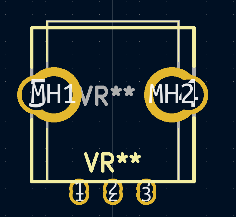
For what are those outer Mounting holes? they are too near to the Faders…make the pcb bigger so there is space for a Spacer/standoff, or use only the 4 inner mounting holes… which i think is enough…
again better 90° corners…
fill out your Shematics “Circuit-Field” right down - dont know the englisch or french word for “Plankopf” … by the way you can design your own “Plankopf”, so you dont see there thing like “KiCAD E.D.,A kicad 6.0.10…”
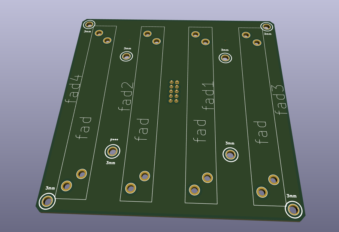
keep out for mounting holes again… (see PB)
dont make outher planes on VDD(+) … mostly there can happen problems when mounting the thing to a panels, better use Ground-Planes…
When looking on your FAders Footprint, and on the DAtasheet for the RA6020F then i am not sure iff the pinout is correct (the datasheet is bullshit…) but i guess you imported the Symbol and Footprint from mouser or something…then i guess its oky…
also use the design-rule check function (in a shematic and PCB-Editor)
i did not looked in the other kicad-projects… but i guess its the same - a bit overwork needet..