It was just for fun. If you are interested in teh codez, you can have them 
Best regards,
Peter
It was just for fun. If you are interested in teh codez, you can have them
Best regards,
Peter
Nice soundtrack and nice display. Wasn’t Wilba recently asking the forum to convince nILS that the new designs need larger displays? Well, this might convince him a little bit. Although only the resolution got higher, not the dimensions.
Thanks
The display looks fantastic and fits perfectly in the MB6582 display area (“raiser veroboard” needed).
It is my hope to convince TK., that this is the perfect upgrade path for MBSID V3, so all we MB6582 users don´t need to build a new frontpanel (which is expensive) and my “Construction Phototutorial” does not get obsolete before MBSID V4 :-).
I´ve just managed to get better timings, there is very slight flicker going on now, which is only visible when there are big bright areas displayed (e.g. “full on” display).
Bye,
Peter
Well, somebody knows how to code  Any progress with the VFD for the MB6582?
The VFD for the MB6582 works fine - watch the photo tutorial, will update it soon :).
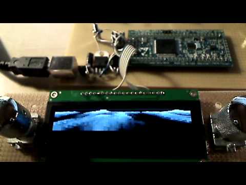
Had an optimization idea - the resolution is now quadrupled to the displays´ native 256x64 pixels (formerly 64x64 stretched) without noticable speed loss - also I recorded this a little bit closer and in HD, so you can see all pixels :-).
The music is a takeout from a rainy afternoon synth jam
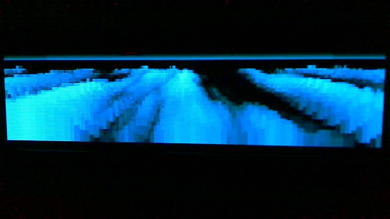
Also, the codez are now in the repository (mios_test/app_lcd/ssd1322).
If anybody has got an idea for “smooth” live updating of the heightfield for different views -> plz contact me :-).
Now, on to more serious things
Bye,
Peter
this is great, and definitely along the lines of what i’m looking for in my next project. so it’s about the size of a 2x20 character lcd? any chance you have some images with just text on it? as in, what 4 or more lines might look like.
Hi ultra,
Dimension-wise, it is more like a 4x20, i put it in the MB6582 just to hypothetically test if it would fit for MBSID V3 :whistle:
http://img4.imageshack.us/img4/2223/256x64inmb6582.jpg
Regarding the font… no codez ready right now to render them, but it will happen at some point in time
If you have a look at the Dave Smith “Tempest” videos, you can get a glimpse of how fine this thing looks
Greets,
Peter
thanks for the reply. i did watch the video and it looks great. i am wondering how many characters in both directions you can get out of this, and how easy would it be to design my own simple graphics for it. i know you don’t know until you’ve written in the code, but let me know when you do. a single one of these might fit the bill just fine. also, could you have characters in different shades? so some look lighter and some are darker.
thanks,
ultra
edit:
also, could you please link me to where i can get a data sheet? i’d like to get the exact dimensions so i can draw it up in CATIA and see how it would fit into my design.
Hi Ultra,
Thanks!
As soon as my seq is done (TK. helped massively lately, thanks!), i will concentrate on this, promised
Regarding the datasheet: here you go: http://www.newhavend…2-25664UCB2.pdf
There are also two slightly differently sized versions available, both being a 256x64 oled with 16 shades of blue/yellow.
Regarding the fonts - everything is possible, even differently shaded (and antialiased) fonts…
Using a 8x8 font, you could fit tiny 32x8 characters (which would be great for a multichannel “tracker”, old amiga noisetracker style, btw. :), )
also possible would be something like 20x5 characters (12x12 px font) plus some leftover border pixels
or better legible and smooth-looking 16x4 characters (16x16px)
…it totally depends on the project!
Regarding graphics access… it is quite easy… you position your “cursor” and then write 2 bytes (4 pixels) “en bloc”. The cursor then advances to the next 4-pixel position, so for a full bitmap dump, you need not reposition the cursor manually. Using double-buffering and this buffer-copying technique, it was possible to yield 30 fps on the display with some calculation in the background (voxel space)… On the other hand it is difficult to manipulate a single pixel, as there is no read access… you either have to know what the neighboring 3 pixels look like (big memory buffer, bad) or you write everything… Which is totally ok for bitmaps with a width of a multiple of 4.
To be honest, it needs to be said, that we would need moar testers for this display, as we had certain initialization problems at first (and the newhaven tech docu is not, ahem, gold quality :-))
Also, as the price is really ok, one could drive more than one display, depending on the projects needs.
Greets!
Peter
Edit:
here is a picture of a “pattern” demo, so that you can assess the “16 shades” better:
thanks for the info. i’ve been meaning to learn about writing drivers and such (right now it’s beyond me), so maybe tinkering with your code will be a good place to start. these seem to fit every requirement i have for a display for my project. i found that newhaven has a 2.8" version of your lcd, and look how perfectly it fits into my case:
Looks great
You may need to ask Thorsten, how it is wired up correctly, as I may have forgotten it by now (or never ever completely understood it :-)). I have a working prototype in my drawer though and a high-res cam
The display itself is great, has high contrast and a very stable image, even when viewed from the side at an angle.
Greets!
Peter
i have a pair of these arriving today! can someone plz tell me how to connect them to a lpc17?
ultra
nm i think i figured it out
hawkeye,
do you remember if you used 2.5v on the data lines? i got an LM317 for power now, and that’s working fine. but occasionally this thing isn’t working, and i think it’s b/c of the current draw from the resistor dividers i’m using for the data. maybe i won’t kill the lcd if i connect those directly to the core?
ultra
Hi,
TK and me powered the whole thing with 3.3V for the first 10 minutes and it did not blow up - so 3.3V on the data lines may be ok, I hope, but no guarantees
The current board, which TK soldered in a quick session has voltage dividing resistors on the data lines.
What helped for me was a 100uF capacitator buffering the 2.5v suppply voltage, the picture was quite “unstable” before, much like a flickering oldschool tv set
Greets,
Peter
What helped for me was a 100uF capacitator buffering the 2.5v suppply voltage, the picture was quite “unstable” before, much like a flickering oldschool tv set
Which makes sense considering the load of an OLED depends mostly on the number of lit pixels, which can fluctuate quite heavily 
Which makes sense considering the load of an OLED depends mostly on the number of lit pixels, which can fluctuate quite heavily
i did some research and i found the 74hc4050. it’ll convert a higher voltage to whatever voltage you power it with, as far as i can tell. so i ordered some of those and a couple 2.5v regulators. so a 16 pin chip, a vreg, and two caps should solve the problem.
i can’t figure out why, but sometimes the voxel demo works just fine, and other times the display won’t turn on at all. and the core flashes the led 3 times and shuts off when it’s not working. i think it’s maybe current draw and hopefully the 4050 solves the problem. i’ll post a schematic when i put it together later this week.
ultra
edit: also i wanna add that i didn’t use any caps when i was testing it on a breadboard, and it didn’t seem to flicker. weird.
Hi Ultra,
good to hear, that the base voxel demo works for you at least sometimes - had some doubts regarding the display initialization, which differs totally from the official Newhaven datasheet
Also, an official connection schematic for this display will enable moar people to use it - great news, thanks for your work!
If I can finish my other project soon, I´d love to do some more coding regarding neat text output on this display :).
Best regards!
Peter
ok, i have what i believe will be a working schem for multiple newhaven graphic OLEDs. i’ll test it later today, but i figured i should put it here in case someone wants to review it in the meantime.
i based this off of tk’s SSD1306 wiring diagrams at ucapps. the diagram for a single OLED is here and the diagram for multiple displays is here.
the only question i really has is if the connections for multiple displays is supposed to correspond to the connections for single displays. if that is the case (which i think it is), then i’ve pulled up the /RS lines to 2.5v with a 1K resistor. if not, then the /RS lines go to RS on the core. but that wouldn’t make sense as it’s being used for DC.
i’ll chime in later on this if i get it working.


