MIDIO128 V3

Hello everyone,

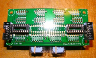
I’m in the middle of building a small Midi controller with the Midio128 V3 / LPC17. It will feature the standard control surface parts (LCD, 6x buttons + 1x encoder), 8x analog pots and three switches (via a self-etched DINX2).

I would really like to add one or two encoders (to send standard midi CCs), but I guess that’s not possible with the current Midio128, right?

TK, do you have plans to implement this into Midio128, or is this “reserved” for a possible MB64e for MIOS32 in the future? Don’t know what the “road map” for MIOS32 is.

Or to ask the other way round: Is there a way to use encoders with MIOS32 / LPC17 ?

Best regards,

Lars

shift MSD enable, pulled up the SD files on open office and found the channels on matrix 1, row 1, C1-C8 mapped to channel 5. However I also noted that while in the matrix, as I changed the pin numbers, the note value also changed, starting with C-2 which is midi note 36. when i called up the default.mio in open office, the note values started with 30 instead of 36. Should the note numbers change to what the CS displayed for the selected pins. I don’t see any other way to set the note numbers.

there are two things which have to be considered: although the file reader allows values in decimal or hexadecimal format, the file writer will always use hexadecimal format (values starting with 0x) - this could be confusing.

Another important thing - and this is what probably was wrong - you have to save your changes, they won’t be automatically updated on SD Card.

It has become evident that I can also modify the tables in the default.MIO file in open office and download to the SD card. In fact, it appears that I could set up everything in open office and download the file to the SD card.

I assume that the SD card will accept the .CSV file?

yes, correct! :slight_smile:

I’m in the middle of building a small Midi controller with the Midio128 V3 / LPC17. It will feature the standard control surface parts (LCD, 6x buttons + 1x encoder), 8x analog pots and three switches (via a self-etched DINX2).

I would really like to add one or two encoders (to send standard midi CCs), but I guess that’s not possible with the current Midio128, right?

TK, do you have plans to implement this into Midio128, or is this “reserved” for a possible MB64e for MIOS32 in the future? Don’t know what the “road map” for MIOS32 is.

I could add simple support for encoders (sending various CC formats including inc/dec) to the firmware.

In long term the upcoming MIDIbox NG will support similar features, but in distance to MIDIO128 it will have better capabilities to parse and send incoming/outgoing MIDI events (including SysEx and NRPN support).

Or to ask the other way round: Is there a way to use encoders with MIOS32 / LPC17 ?

Of course!

Following tutorials describe the details (read the previous tutorials to understand the basics):

http://svnmios.midibox.org/listing.php?repname=svn.mios32&path=%2Ftrunk%2Fapps%2Ftutorials%2F014_enc_relative%2F

http://svnmios.midibox.org/listing.php?repname=svn.mios32&path=%2Ftrunk%2Fapps%2Ftutorials%2F015_enc_absolute%2F

Best Regards, Thorsten.

TK,

Sorry about the push for details.

I spent some time with ver. 5b - very nice!

I also uploaded the contents of the SD card to open office and looked at the .MIO file. WOW - there is alot of stuff there, namely i noticed 16 sets of matrix maps for 16 channels and note values.

For improving my facility with the CS, i went to M8X8 on the main menu, selected map mode, then set the matrix to 1, pin 1.1 and changed the channel from 1 to 5 for pins 1.1 thru 1.8, saved it, did the shift MSD enable, pulled up the SD files on open office and found the channels on matrix 1, row 1, C1-C8 mapped to channel 5. However I also noted that while in the matrix, as I changed the pin numbers, the note value also changed, starting with C-2 which is midi note 36. when i called up the default.mio in open office, the note values started with 30 instead of 36. Should the note numbers change to what the CS displayed for the selected pins. I don’t see any other way to set the note numbers.

It has become evident that I can also modify the tables in the default.MIO file in open office and download to the SD card. In fact, it appears that I could set up everything in open office and download the file to the SD card.

I assume that the SD card will accept the .CSV file?

Looking good!

johnc

since the above email,

I spent a good deal of time with the CS and the LPC and answered a lot of my questions.

Must admit, it is a wonderful device. Head and shoulders above the old cores, in many ways. I enjoyed just playing around with it.

Other then the tedium of assembling it, should be great for newbies to get started. A couple of questions;

  1. Setting the configuration for an organ is easiest done editing the default.mio file and uploading to the LPC. the operation is very similar to the old “.ini” use, and I guess thats what you had in mind. I suspect that all unused matrix templets can be deleted from a custom .MIO, keeping the default intact for record purposes. yes?

what happens if you setup DINS (non-matrix) which are already used in a matrix in the lPC .MIO file? Which will take priority. The DIN or the matrix? Also if I download a custom .mio file that contains such errors, what will happen?

  1. If I want to configure a matrix using the normal mode, and I want the First note # to be dec. 36, 0x24, I can accomplish this by editing the long string which now has 0x30 in it. yes?

  2. I note that in the matrix setup strings, the OSC1 is checked, along with USB and IN1. what does the OSC do?

  3. If I plug in my Dilink wireless USB adapter into the LPC will it communicate with my wireless router? Since my organ console is 50 feet from the computer location, midi over ethernet would be great, especially if wireless.

Great work TK!

johnc

Hi johnc,

I don’t want to sound disrespectful, but you could answer all your questions yourself (except no. 3 maybe) by simply trying out what you suggest, and report here! :thumbsup:

Best, ilmenator

I could add simple support for encoders (sending various CC formats including inc/dec) to the firmware.

In long term the upcoming MIDIbox NG will support similar features, but in distance to MIDIO128 it will have better capabilities to parse and send incoming/outgoing MIDI events (including SysEx and NRPN support).

Of course!

Following tutorials describe the details (read the previous tutorials to understand the basics):

http://svnmios.midibox.org/listing.php?repname=svn.mios32&path=%2Ftrunk%2Fapps%2Ftutorials%2F014_enc_relative%2F

http://svnmios.midibox.org/listing.php?repname=svn.mios32&path=%2Ftrunk%2Fapps%2Ftutorials%2F015_enc_absolute%2F

Best Regards, Thorsten.

Support for encoders would be great, and quite useful.

I will definitely dive into programming, that was one of the reasons I built the new core, but I guess it will take some time before I come up with something useful.

Speaking of Midio128, right now I experience some heavy jittering with the 8 analog pots, constant bombardement with values (like 3-4 messages every second), some are jittering around a certain value, and sometimes it’s all over the place. I used 10k pots with the 100nF capacitors, and cables are quite short (ca. 12cm)… I guess it’s some kind of grounding issue. Have to try some things over the weekend…

Best regards,

Lars

Hi johnc,

I don’t want to sound disrespectful, but you could answer all your questions yourself (except no. 3 maybe) by simply trying out what you suggest, and report here! :thumbsup:

Best, ilmenator

Ok! I accept the hand slap, but not without comment!

Remember that I am using "5b"the beta ver. Why would the lowest note on an organ keyboard be 0x30? The low C on most organ keyboards is 0x24. Could be an error.

Yes an answer to item 3. would be good.

For those of us that lack the technical insight, we tend to think of such devices as the LPC17 as a black box, hoping that in some way it can make my “stuff” work better. So in reading a feature list as awesome as the list for the LPC it is normal to look for applications in my personal domain. I refer to item 4 above. IMHO, when I plugged the wireless adapter into my laptop, I had to run some config software to set it up. Isn’t it reasonable to ask item 4, since I have no way of knowing or understanding what the firmware can do, or not do.

Enough said!

TK - I appreciate all your hard work and patience with my questions.

Best Regards,

johnc

I will definitely dive into programming, that was one of the reasons I built the new core, but I guess it will take some time before I come up with something useful.

I think that in this case it would be better if you would integrate the encoder handling by yourself - a nice exercise to learn programming :slight_smile:

Speaking of Midio128, right now I experience some heavy jittering with the 8 analog pots, constant bombardement with values (like 3-4 messages every second), some are jittering around a certain value, and sometimes it’s all over the place. I used 10k pots with the 100nF capacitors, and cables are quite short (ca. 12cm)… I guess it’s some kind of grounding issue. Have to try some things over the weekend…

The jitter is normal, the ADCs of LPC17 are really bad, I don’t like them.

This is also related to the LPCXPRESSO design, because the ADC supply input is directly connected to digital supply.

http://discourse.midibox.org/t/topic/16088

Remember that I am using "5b"the beta ver. Why would the lowest note on an organ keyboard be 0x30? The low C on most organ keyboards is 0x24. Could be an error.

It isn’t really an error, but you are right that it makes sense to use a lower note by default.

I will change this in the next release.

  1. I note that in the matrix setup strings, the OSC1 is checked, along with USB and IN1. what does the OSC do?

It means, that events are also sent via ethernet (if enabled).

The supported protocols are explained here: http://www.ucapps.de/midio128.html (search for keywords “Supported OSC Packet Formats”

My opinions about OSC are written down here: http://www.ucapps.de/midibox_seq_manual_osc.html

  1. If I plug in my Dilink wireless USB adapter into the LPC will it communicate with my wireless router? Since my organ console is 50 feet from the computer location, midi over ethernet would be great, especially if wireless.

For MIDI over Ethernet I wrote a proxy, but currently it only works on a Mac.

But you could also ask the developer of the organ emulation that you are using to integrate OSC support.

The “j” in “jOrgan” sounds like it’s based on Java, and Java has already an integrated OSC library.

Accordingly it should be trivial to add such a feature to jOrgan, so that it can be accessed via Ethernet.

Best Regards, Thorsten.

TK,

Thanks!

I think that I am good to go for awhile.

johnc

today I played around with the pots a bit more: tried different pots and values (1k, 10k), connected only one pot at a time, inside/outside the case… and after reading your post now my conclusion is the same: must definitely use the AINSER64 if I want to use analog pots with the LPC17.

Ok, installing xcode right now …. :thumbsup:

Thank you Thorsten!

Lars

Just me again, wanted to let you know I’m still alive, I’ve been working with my dad on building the box for all my buttons, we got the top done and I just got finished hand wiring one of the matricies. It’s a very time consuming process I have discovered. But it seems like it will be worth it. I’ll post pics some time soon. I only have one question for you now, Is there any way to set the fixed velocity to something lower than full? Or have the velocity of all outgoing notes scaled by one knob?

I finished the other matrix today, now I’m just waiting on my dad to finish the bottom of the box. I also figured out that if you have two matricies and you push something on both of them at the same time, it triggers the DIN as per the column on the second matrix, I don’t know if it did this in mode 0, but If I just set all the DINs that I’m using for the matricies to send out 0xFF it’s fine.

MIDIO128 V3.006 is available now

Finally the “128” also stands for 128 analog inputs! :slight_smile:

MIDIO128 V3.006
~~~~~~~~~~~~~~~

o support for two MBHP_AINSER64 modules: up to 128 analog pins can be scanned!

o improved MIDI OUT throughput
[/code]


Best Regards, Thorsten.

Nice!!!

I’ll try that as soon as I finish my small “ainser8” board

Thanks TK !!

A SysEx transfer issue at port OUT1 and OUT2 has been fixed in MIDIO128 V3.007:

MIDIO128 V3.007
~~~~~~~~~~~~~~~

o corrected SysEx output for LPC17
[/code]


Best Regards, Thorsten.

TK,

Today I finally got midio128 ver 3.007, and jOrgan ver 3.14 working together. Big problem all along was that of midi channel mis-match. 0-15 vs 1-16. Had to do some juggling.

With midio 128 on the LPC, is it possible to make the monitor display of inputs and outputs last a bit longer. Currently it is too fast to read.

Other then the above, the LPC is doing a fine job. It would be great if the midibox DINS and DOUTS and Pic8 cores all had polarized connectors.

Thanks TK for a great device, and the willingness to help me get my LPC up and going.

Johnc

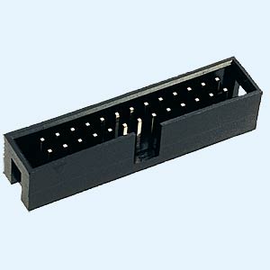
It would be great if the midibox DINS and DOUTS and Pic8 cores all had polarized connectors.

This is easy to implement - after all, you’ve built the thing yourself, so you can use any connector you want. The one in the picture for example is what I use.

On the DINX4/DOUTX4 module, there isn’t enough space for polarized connectors… :-/

But at least I considered this on the new MBHP_DIO_MATRIX module, because meanwhile I don’t want to miss them as well! :slight_smile:

Best Regards, Thorsten.

Thanks for the comments guys.

You are correct TK, the DIN4X and DOUT4X are small. Perhaps Smashtv would entertain a slightly enlarged version. Wouldn’t take but a couple of millimeters.

A few comments about the mios studio. The midi monitor does not display the complete config for the matrixes - matricies, and what it does display is mixed up. Also please comment about the speed of display of inputs and outputs on the mon display on the lcd. It flashes much too fast to read.

Last question - Remembering that i am working with an LPC and a PIC8 tied together. With mios studio loaded, either device can be querried. with the midio128 V2 screen on the monitor, what happens if you send or receive with the device number set to the LPC instead of the pic8?

Johnc

On the DINX4/DOUTX4 module, there isn’t enough space for polarized connectors… :-/

But at least I considered this on the new MBHP_DIO_MATRIX module, because meanwhile I don’t want to miss them as well! :slight_smile:

Best Regards, Thorsten.

TK,

The MBHP_DIO_matrix would have saved me lots of trouble 4 months ago as I planned encoding 4 keyboards. I followed the same approach, but with a DIN4X and DOUT4X, ending up with encoding capability for 16 matricies which is over kill. I ended up with 4 matricies, three for keyboards, and one for contacts on the SAMS which had to be wired with the diodes on each SAM. This was very “wireing” intensive, whereas the new keyboard matrix would have simplified things greatly. Thanks for your continued work in this area.

have you given any thought to an output matrix? Consider this - Each SAM has 12vdc available on the device which is sufficient for installation of two transistor drivers on each SAM, one for each magnet, with a very limited PIC controller programmed to have one input whereby one magnet is driven with an “on” signal, the other with an “off” signal. The output matrix would do all the decoding and activate each matrix location based on conventional DOUT coding. Actually, why couldn’t a bistable flip-flop be used, each side driving a magnet, the flip flop changng state with the “on”/“off” signal from the output decoder. just a thought. Would really save a lot of wiring and hardware. Since each SAM has a pcb attached, the additional stuff could be installed on the pcb. For SAMS that come with a connector already installed, the mod could be done with a small plug on board, with no work needed on the SAMS pcb.

Going a bit further, currently, it takes 2 DOUTS to drive SAMS, for 64 SAMS total with 4 DIN4X. the same “flip-flop” driver on a plug on pcb could be used with conventional DIN4X which would permit 128 SAMS. This would eliminate the ULN driver addition to the DOUT cards.

Does this make any sense?

johnc

I guess a simple “what Ilmenator said” won’t do here… :wink:

DINX4: Box headers can be used on the input lines also with slight modification (shave the corner off of J3 and J6 with a sharp knife else they will run into J1 and J2)

DOUTX4: No mods on any connector positions - drop in some box headers and solder!

PIC CORE: J8/9 will likely run into the PIC socket (depends on the brand of the header). Shave a bit off the corner of the header with a sharp knife or file and problem solved.

All other connector positions fit without modification.

You are correct TK, the DIN4X and DOUT4X are small. Perhaps Smashtv would entertain a slightly enlarged version.

Those layouts were done with an eye towards build cost and drop in compatibility (including size/mount hole spacing) with the official layouts.

Low cost shrouded/box headers are a relatively recent thing, but that is no reason to assume that I did not consider them while playing trace tetris. :wink:

Wouldn’t take but a couple of millimeters.

And some design time, and a few hundred $USD in NRE charges/photoplots/screens, and the associated cost to stock two variants of the same module as board and kit etc…

That does not mean I won’t do some smaller prepaid bulk-order style fabrication runs of whatever is needed, and I’m always ready to help turn a schematic into a board layout on my dime for any public MIDIbox related project.

Best regards

Tim