Check out the creation of Doc! ![]()
He wrote some interesting comments to his design, the english translation in bold font:
Wie häufig im Forum erwähnt, habe ich (inspiriert von Axel) eine Midibox LC mit 16 Kanälen aufgebaut. Betrieben wird das Ganze unter Cubase, was mittlerweise mehr recht als schlecht auch funktioniert. Damit ich 16 Kanäle nutzen kann, habe ich die Assignement - Tasten, die Fader Channel & Bank tasten, sowie die Shift-Tasten mit Dioden verkoppelt, so das ein tastendruck stets beide Core Module bedient. In der Aux-Section sind aber die Taster der rechten 8 Kanäle noch mal ohne Diode auswählbar, damit ich mir immer schön die Kanäle 1-8 und 9-16 darstellen kann. Dies funktioniert zumeist recht passabel.
Nun zu den Bildern:
As mentioned earlier somewhere in the forum, I’ve build this 16 Channel midiboxLC (inspired by axel). The host application is Cubase. Because of the missing function in cubase to control an extended controller, I’ve chained the common switches of the two 8-channel sections (like Bank left/right, flip, shift, …) with diodes together. Now I can control two LCs with one function button. In the AUX section there are all buttons for the right module seperately (without diodes). In this way I can make my desk ready for channel 1-8 on the left module and channel 9-16 on the right module. It’s not perfect - just a workaround till further notice from Steinberg (Update).
The pictures:
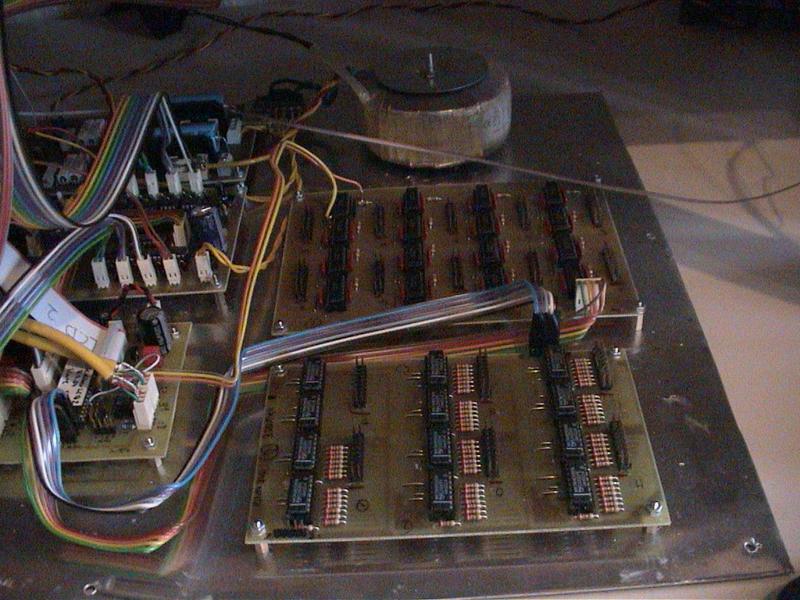
zeigt das Mainboard des Mixers. Ich habe alle DINs und DOUTs auf extra Platinen gelayoutet, damit ich konsequent 20-polige Pfostensteckverbinder verwenden kann. Alle Verbindungen sind gesteckt, damit das Board oder einzelne Platinen zu Wartungszwecken entnommen werden können.
shows the mainboard of the mixer. I’ve build a whole board for all DIN and a board for all DOUT modules so that I can consequenmtly use 20ch ribbon-connectors with ribbon cable. All connections of the mainboard have plugs. By doing this, I can unplug the whole mainboard or single boards for support reasons.
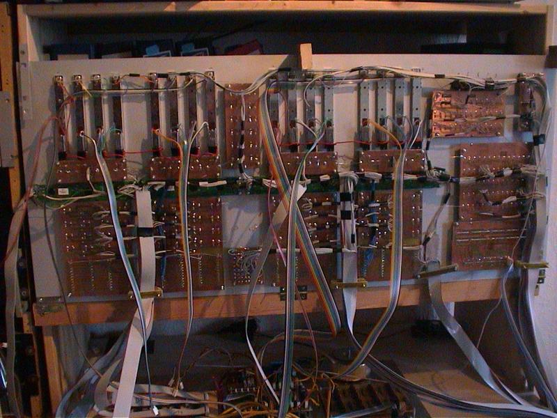
zeigt die Gesamtansicht der verdrahteten Frontplatte. Ich habe mich diesmal dafür entschieden, sämtliche Bedienelemente (außer Motorfader) auf eigenen Platinen zu entwerfen. Die Kabel sind hier zwar gelötet, das Layout entspricht jedoch weitestgehend der Belegung auf meinen DINs und DOUTs, so das die Verkabelung rasch von der Hand geht.
shows the total rear view of the wired frontpanel. This time I decided to build boards for all control elements except the motorfaders. At this end the wires are soldered, but the layout follows almost the connectors on the DIN an DOUT boards. This way the cabling is a bit easier …
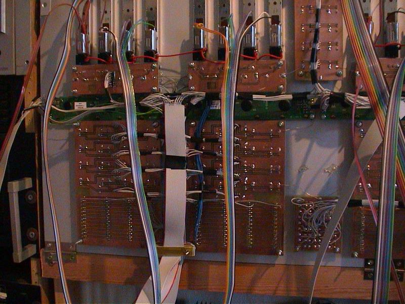
zeigt eine Detailansicht der Encoderplatinen und der rec/mute/solo/select/vu-Meter - Platinen.
shows a detail view of the encoder-board and the rec/mute/solo/select/vu-meter-board.
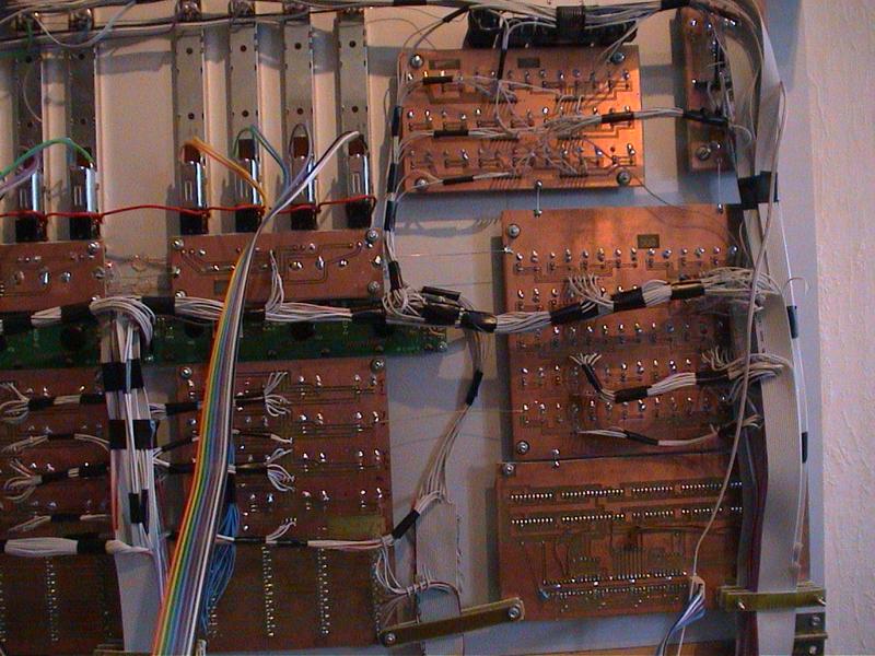
zeigt eine Detailansicht weiterer Schalterplatinen, sowie die Jog-Wheel Platine und die LED Anzeige. Auf der Jog Wheel Platine ist außerdem noch ein ULN Treiber angebracht, der die 12V Birnchen für die Transportschalter antreibt (war ne Idee , die ich von Dir aus Deiner Relais-Steuerung entliehen habe…).
shows a detail view of several “switch”-boards, the jogwheel-board and the MTC LED board. The jogwheel-board also hosts a special ULN driver for the 12V-lamps of the transport-buttons (this was an idea borrowed from Thorstens relais-option for the MIDIO128). You can use common switches then without soldering leds into them.
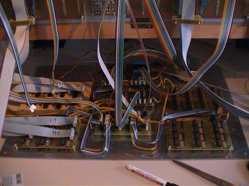
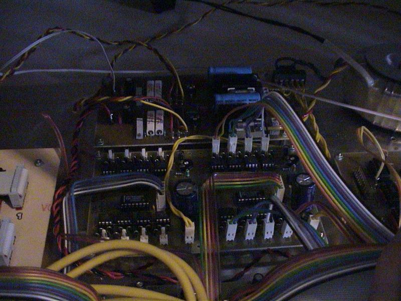
zeigt eine Teilansicht des Mainboards mit den DOUTs und DINs für die rechte Seite. Hinten erkennt man auch das Netzteil und den Trafo. Beim Netzteil habe ich ein regelbares Dualnetzteil (mit 2xLM723, 5V, 12V) entwickelt, daß mit einem 2N3055 als Treiber (nicht auf dem Foto) mindestens satte 3A pro Spannung liefert. Die 12V verwende ich nur für die Transport Birnchen. Die Spannung für die Fader kommt aus einer eigenen Wicklung des Ringkerntrafos. Dieses etwas aufwendige Netzteil hat den Vorteil, dass es sehr genau abgeglichen werden kann und ausserdem die Spannungen stets konstant hält (auch wenn alle 16 Fader arbeiten.).
shows a detail view of the mainboard with the DIN ond DOUT boards for the right half of the box. In the back you see the transformer an the power-supply. The power supply is a own cration. It’s a regulated dual-power-supply controlled by two LM723 regulator ICs and powered by seperate 2N3055 transistors. The output is 3A per voltage (more than enough). You can adjust the voltages (5V and 12V) very exactly with this application. It’s very stable, even when all 16 motorfaders are moved parallel. The 12V is only used for the transport-lamps. The power for the mf-modules is on a separate tapping current of winding on the toroidal core transformer.
zeigt die beiden MF Platinen und das Netzteil.
shows the two mf-boards and the power-supply
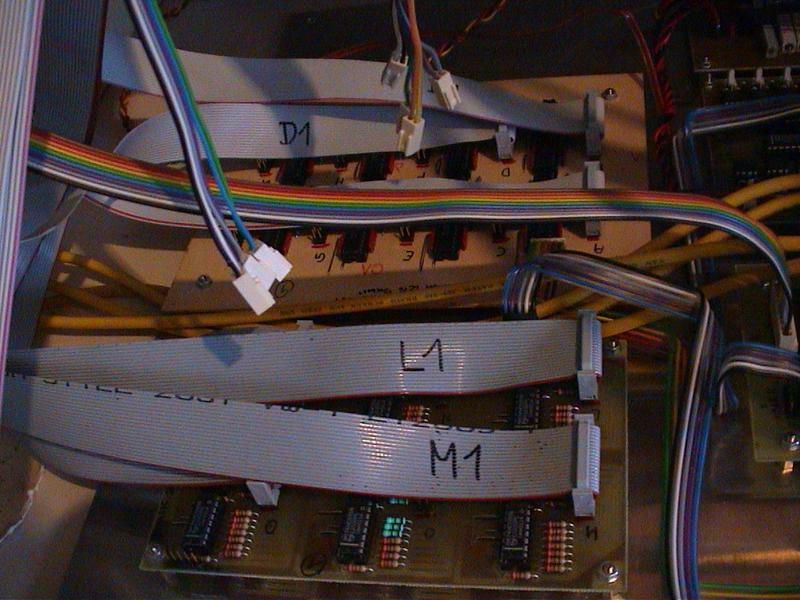
zeigt Detailansicht DINs und Douts linke Seite.
shows a detail view of the left DIN and DOUT boards
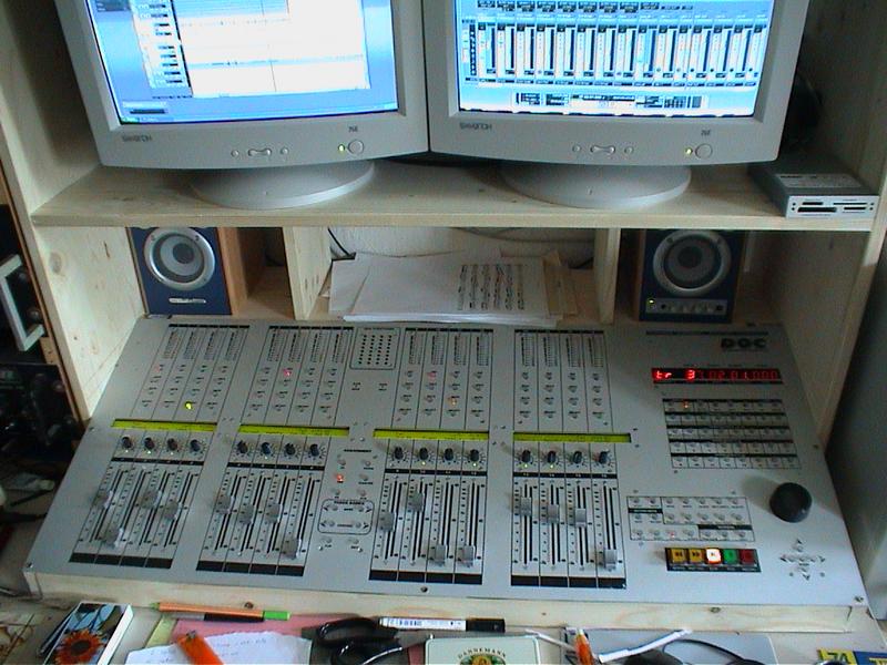
zeigt eine Totalansicht der Frontplatte. Die Platte kam übrigens von Schaefer. Der Aufdruck stammt von einer T-shirt Kopierfolie (aufgebügelt) und wurde anschliessend mit KFZ-Klarlack überzogen.
shows the total view of the frontpanel. The frontpanel is from “Schaefer”. The lettering was layoutet on the pc and the printed on a special transparency for an iron (german: T-shirt-Bügelfolie). After that it was coated with clear varnish (for cars).
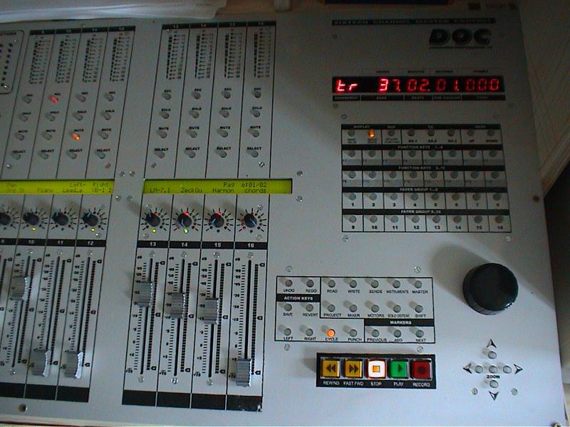
zeigt die rechte Seite der Frontplatte.
shows the right half of the frontpanel
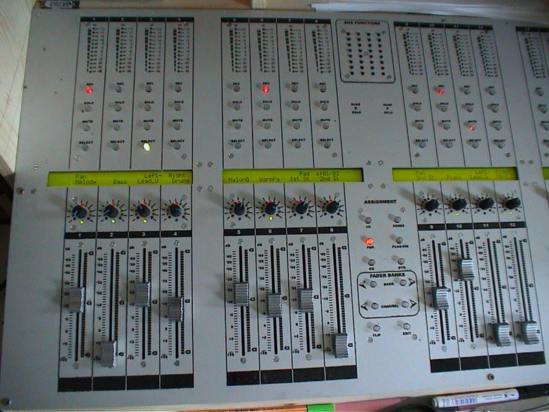
zeigt die linke Seite der Frontplatte.
shows the left half of the frontpanel