Great TK, I assume what wasn’t working (reliably) now is?
I can’t confirm this, since I don’t have a setup ready which would allow me to test longer SRIO chains.
Currently I strongly focus the firmware development and test it with existing hardwares, such as MBSEQ, MB16E, MBLC
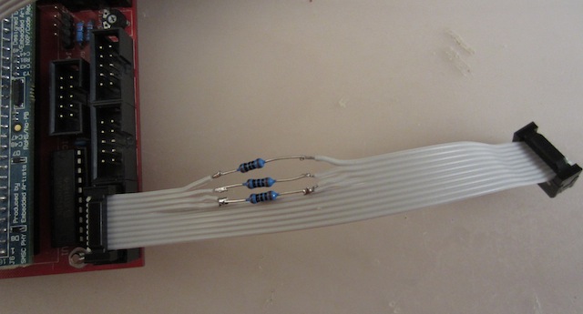
The modified cable was only an idea how we could provide a simple solution without PCB re-design (which could take months till it’s phased in - and many people would still own the previous PCB version - therefore no feasible ad-hoc option)
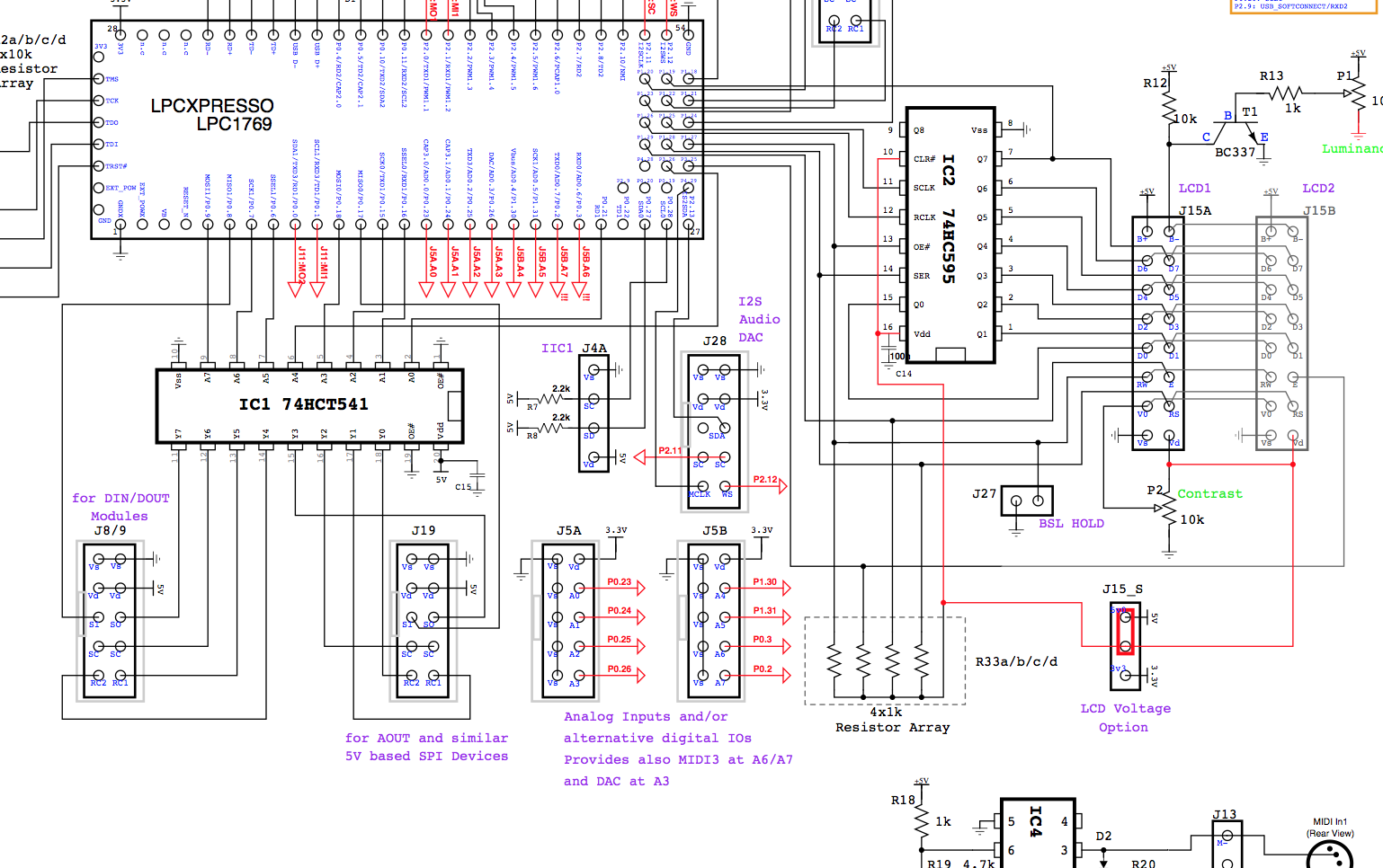
If I’m correct regarding the signals going to the SR’s, the RS line is non critical as it’s transition latches the register data to the output pins (in the case of DOUT), and samples the input pins into the register (in the case of DIN). If there is bounce on this line it does not change anything.
You are probably right. On the other hand, spikes on the RS line could probably influence the SC line as well.
This is just an assumption, as mentioned above I haven’t checked this by myself.
By adding resistors to both lines we should be at the safe side.
Does this mean no source code for STM32, or no documentation?
The release package contains a binary for STM32, but I won’t mention this in the MBNG documentation as a HW option, because the “if” and “whens” could confuse newbies too much.
Main reason is, that the performance of STM32 is worse, so that the MBNG firmware doesn’t show the same excellent latency than on a LPC17 core (in fact benchmarks are showing a performance of only ca. 50..60% of a LPC17 core).
Another reason is, that since some months the MBHP_CORE_STM32 module can’t be purchased from SmashTV anymore.
However, for experts (like you) it shouldn’t be a problem to handle this.
Best Regards, Thorsten.