Because my Waldorf Midibay became too small for connecting all of my MIDI equipment, I went ahead and designed my own MIDI matrix / programmable patchbay. The modular MIDIbox Matrix has up to 56 input and 56 output ports and provides a smart solution for the fact that not all MIDI equipment is usually located in the same rack or corner of the studio space.
MIDIbox Matrix features break-out boxes (BOBs) that give access to 4 MIDI in and 4 MIDI out ports at a time. These are connected via 9-pin serial cables to the main unit and are designed to be conveniently placed in the back of your rack, e.g. attached to the inner sidewall of a rack enclosure with screws or velcro tape. This means that instead of running 8 MIDI cables to the MIDIbox Matrix in order to connect four synths, you only need a single, cheap serial cable from your side rack to the center point of your matrix.
Two BOBs each connect to a single I/O board, which does all the level shifting and signal refreshing. Up to seven I/O boards can be attached to the heart of the MIDIbox Matrix, an FPGA-based switching and routing logic that is controlled via a core board such as the STM32 or the LPC17.
As the system is highly modular, it is possible to start with a low port count (4) and then increase the number of available ports by simply adding I/O boards and BOBs as needed. Fully loaded, i.e. offering 56 input and 56 output MIDI ports, the MIDIbox Matrix consists of
1x FPGA board
7x I/O boards
14x BOBs
plus a core board and the PCB holding the user interface.
Software-wise, this is almost ready - everything works as expected, just the PANIC button has to be implemented in the next weeks, and some code cleanup will be necessary. You can find more documentation in the Wiki if you are interested.
have read the mb_matrix-wiki. looks like a really interesting project. is it designed for the “CoreEP2C8” ? i suppose you can program the fpga-daughterboard with your fpga-mainboard ? eventhough i like your modular concept, i would go for something like 2 I/O-Boards and 4 BOBs (BlitterObjects ? :D). would it be possible to connect them directly to the stm32-core ? are you planning to upload your source into the mios32-repository ?
and yes as a altium-user i must admit, that i really like your kicad drawings!
eventhough i like your modular concept, i would go for something like 2 I/O-Boards and 4 BOBs (BlitterObjects ? :D).
That’s a design decision based on my specific “studio” setup and the costs involved in fabricating small boards in larger quantities (as opposed to large boards in smaller quantities). Also, with this specific implementation it is possible to use cheap serial cables that are available everywhere. Serial cable plugs can easily be secured against falling off their sockets, which is nice when some of your gear is mounted in racks with wheels.
would it be possible to connect them directly to the stm32-core ?
Absolutely yes. A BOB (Break-Out Box) can be connected to the new STM32F4 core board via J11E. It is a nice alternative to the I/O board that you can order together with the core board from SmashTV (and you only need one for all four I/O ports). I hope to find some time this weekend to design a little adapter board (from 10pin IDC connector to 9pin DSUB) with level shifting for the MIDI out signals. I am not sure it is a good idea to keep the MIDI signals at the 3.3V level if distances are getting larger. At a 5V signal level I have tested 25m by chaining the five serial cables I have right now, and this worked perfectly. I don’t even think that’s the limit, but again this was at 5V signal level, which is what is specified in the MIDI standard if I remember correctly.
are you planning to upload your source into the mios32-repository ?
Yes, the MIOS sources will eventually go there, but there is very little magic involved - it is mostly based on the available modules for accessing the SD card, the SCS, and the shift register handling. Btw, I am developing this on an “old” STM32F1 core, and in terms of performance I guess that even a PIC core would do.
I have enough hardware synths to warrant getting some of these as I kind of sort of should get a MIDI patch bay at any rate. The old Mac G5 tower runs some old-school Mac PPC software like SoundDiver, Galaxy and such, the PC runs MIDIquest and separate editors for the XV-5080 and a few more. The i7 MBP runs Cntrl, the editor for the Radias, MIDIbox Studio and what not. Something like this would help me. This is even before I think about the iPad and those editors and things…
I was pretty sure this would be something for you, too…
I’ll get back to you once I have received the next version of the FPGA boards which will provide a means for MIDI activity monitoring on all in and out ports.
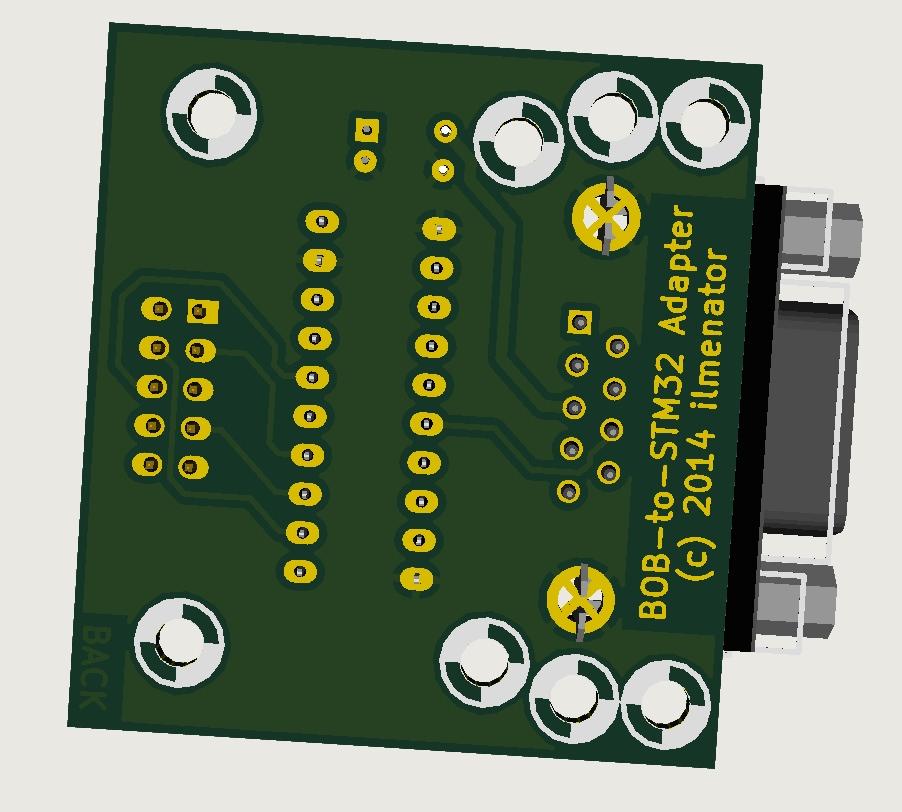
I hope to find some time this weekend to design a little adapter board (from 10pin IDC connector to 9pin DSUB) with level shifting for the MIDI out signals.
This adapter board connects to J11E of the STM32F4 discovery board. With this in place, you can use the BOB as a regular four port MIDI I/O extension with the discovery core board.
thanks ilmenator for your explanation. my understanding is, that i could connect only one BOB to J11E of the stm32core, which will give me 4 midi-ports (in/out). they work already with 5v in my case. dont need the smashtv-version, as i could easily do (and want) my very own. if i would need more than the 4 midi-ports, lets say 16, i would need the fpga-board with i/o-boards, so im obviously not getting around having one fpga-board (btw is it the “CoreEP2C8” ?) and probably 2 i/o-boards + 4 bobs, right ?
im fully aware, that your studio-setup requires 56 midi-ports. thats absolutely fine to me, but i was asking for a version for my setup, where 16 midi-ports should be enough for a start, as i could connect even more, if i wanted too…
I think there is a misunderstanding here. The MIDIbox Matrix routing functionality is not running on the STM32 core, but on the FPGA. It is a stand-alone project and not a hardware extension to other projects. The STM32 core in this project only controls the routing and provides a user interface as well as program storage. So, even if you only wanted a 4-port router for this project you’d still needed the FPGA board. (In which case it would make more sense to go for a software-based router running on the STM32 core itself).
If you want more MIDI ports in your other applications like NG, SEQ or whatnot, you need the IIC board.
However, if you only want to spare the space for two of SmashTVs MIDI I/O boards, or if your MIDI ports should be physically away from your core board, then the BOB in combination with the above adapter board is also an option.
yes i got it now! this is why i think, your project is really great! i was asking for a 16-port-version (16 midi-ins/16 midi-outs), in which case i would need the fpga-board, 2 i/o-boards and 4 bobs. i think that this would fit nicely in my rack! if i would decide, that i need more than 16 ports, i would need another unit. i believe 16-ports will be the maximum for a 19-inch-device. had something like that in mind for quite a while now, but never had a real thought of it. i will keep watching here for any updates anyway. is the fpga-daughterboard the “CoreEP2C8” ? they really have a lot of interesting stuff there btw. are you planing to publish any schematics, apart from the sources for the stm32 and the fpga ?
If you want all MIDI ports on the back of your rack enclosure then you might want to think about using SmashTV’s MIDI I/O board for that, as the BOB has MIDI sockets on two opposite sides.
Take a look in the Wiki and at the BOB section and you can already see what kind of documentation will go there. Schematics will be available, and I am planning to provide PCBs to those interested - together with the BOM it should then be very easy to build your own MIDIbox Matrix. I will also provide the design files for the acrylic enclosure of the BOBs. I’ll reveal the FPGA daughterboard details once the MIDI activity display has been tested on the next FPGA board iteration.
thank you for your information, i have to be a bit more patient for the moment, as its still in work, but it definetely looks like a very useful project for me already…
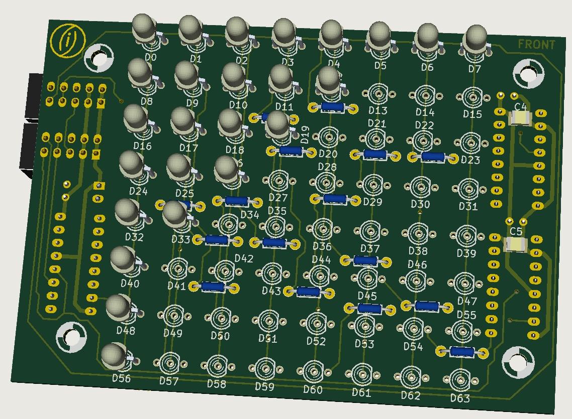
A little update: I have received the second version prototype PCB of the FPGA board, the “heart” of the MIDI matrix. A quick test revealed that the communication works as expected, and I get feedback from the FPGA board to the core about input and output activity of the MIDI ports. Next on the list is an activity display board, essentially an 8x8 Duo LED matrix board.
The first seven rows will indicate MIDI port activity, the last row will display “virtual port” activity, e.g. activity of the mergers. This board might also be used by other projects that require some form of Duo LED matrix. It is located anywhere in the DIN/DOUT SR chain and connects to J8/J9 of the core board.
…excellent news! the duo-led-matrix-board looks quit neat. just one question: is the copper rest ring for the duo-leds big enough ? on the picture (bottom side) it looks like its too small and then it gets diffcult to solder. usually i add 30 mil to the hole-size, which gives me a 15mil copper rest-ring around the hole. with that i get good solder results. not sure how to do that in kicad, but im quite sure, that you can setup the pad-sizes somewhere. also i like the sil-header format. 10-pin is what i use for my projects as well.
No problem, it’s always good to have a second pair of eyes looking at the details! If I go for this option (not sure yet, the alternative is an RGB LED matrix module that consumes a little less front panel space) I might revise the pads.
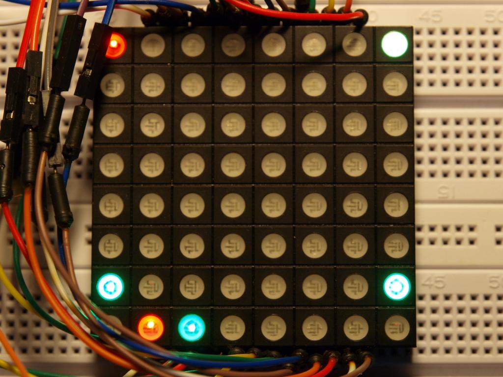
So after all I went with the RGB LED Matrix module to indicate MIDI activity on the 56 in-ports (red) and 56 out-ports (green) in the upper 7 rows. The lowest row displays MIDI merger activity, the two inputs of Merger 1 on the first two LEDs in red, and its output on the third in green. The same goes for Merger B on the following three LEDs. The last two LEDs in the last row are not involved for now. Also, I’ll have to think of what to do with the blue color…
In the picture you can see that a MIDI signal is coming in on port 1, which is then forwarded by the Matrix to ports 8 and 49. It is also forwarded to input B of Merger 1 (red LED in the lowest row), which then passes it on to its output (green LED next to it), which is connected to MIDI out port 56 (green LED in the lower right corner).
I have the RGB LED Matrix module working on breadboard for now, proper PCBs are on their way and should arrive next week or so. Apart from a little code cleanup, the Config page in the menu, and a Panic function, everything I wanted in this router is functional by now. :happy: