Album by Sauraen
Gallery category: midibox-gallery
Sauraen and Oikanys make what they hope will be the world’s most powerful SID-based synthesizer. MORE CONTROL!
MIDIbox ASIDITY Front Panel Mockup
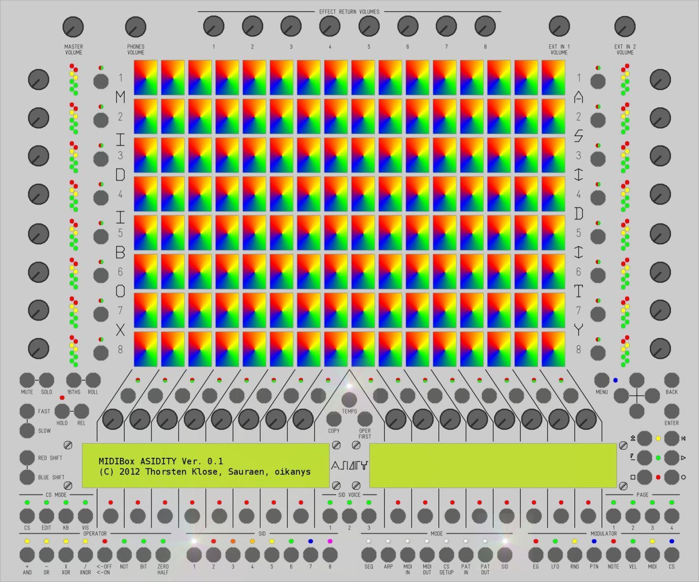
See my post in the Design Topics forums for details:
/topic/16471-midibox-asidity/?do=embed" frameborder=“0” data-embedcontent=“”>
MIDIbox ASIDITY Case
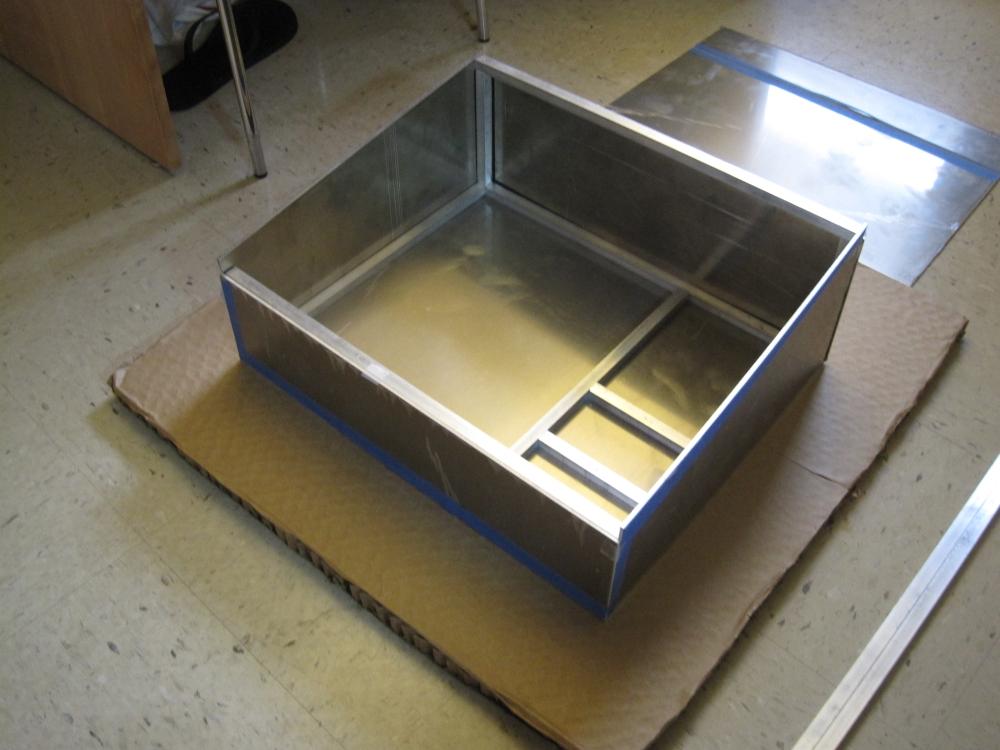
I haven’t drilled the screw holes yet, so this is held together by gravity and Scotch tape. /public/style_emoticons/default/smile.gif" alt=“smile.gif”>
MIDIbox ASIDITY Case with power supplies
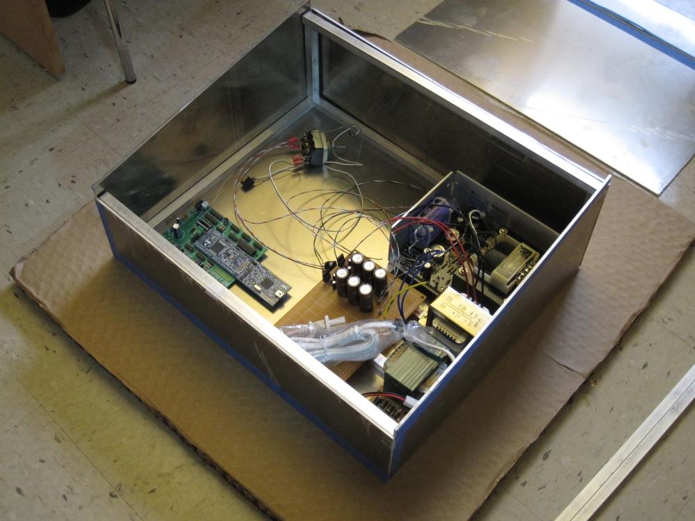
I just threw in the power supplies we’re using for scale. +5V @ 9A, +/-5V @ 2A, +12V @ 4A.
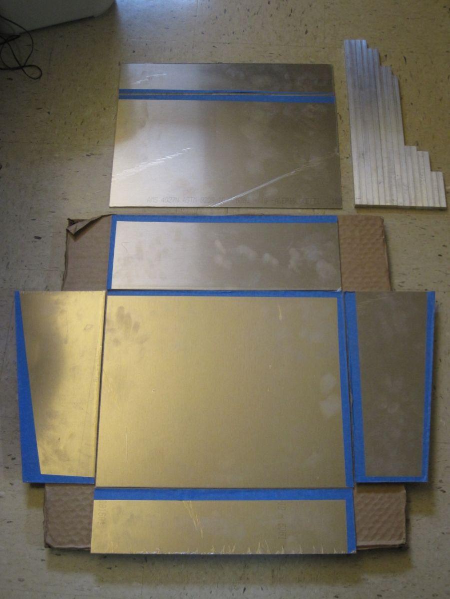
MIDIbox ASIDITY Case cut aluminum
LPC17 core
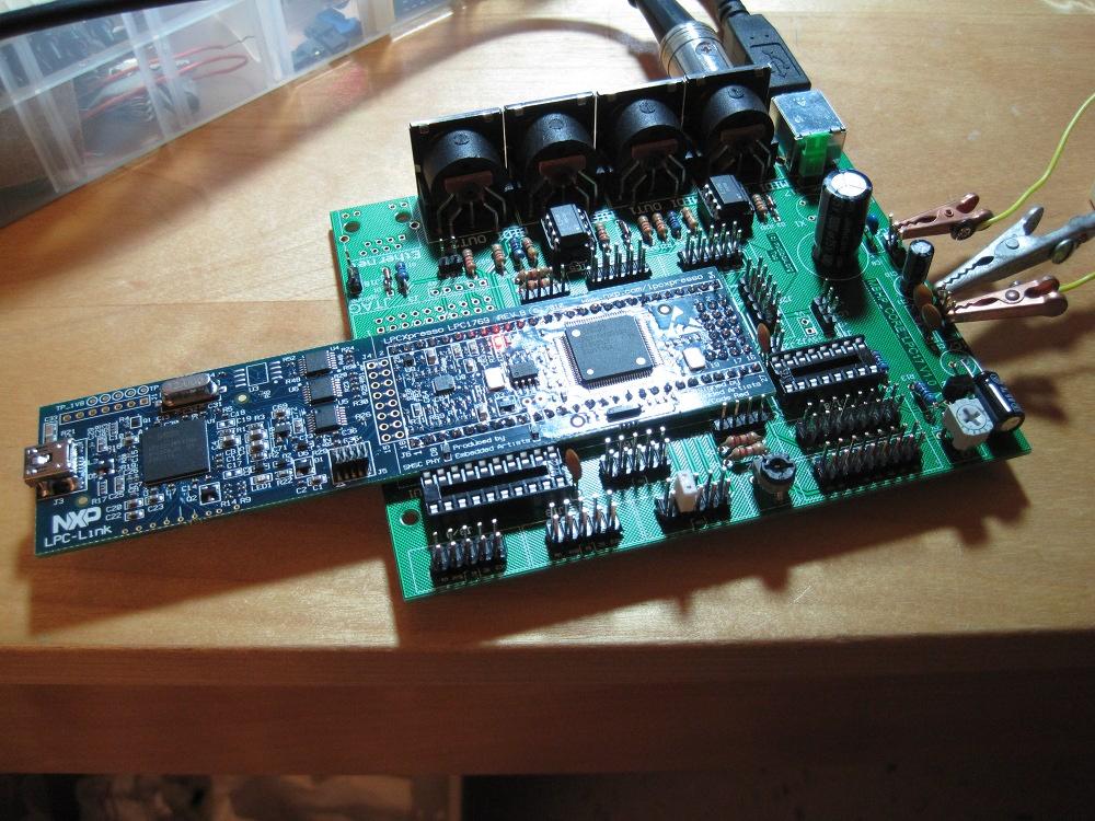
MBHP_SIDFB Board
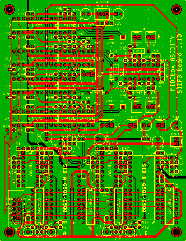
This is the final (ordered!) version of our design for the SIDFB module, containing two SIDs, six channels of digitally controlled feedback and audio outputs per SID, and a CD4052-based circuit to switch between four pairs of filter capacitors.
SIDFB Board with Chips
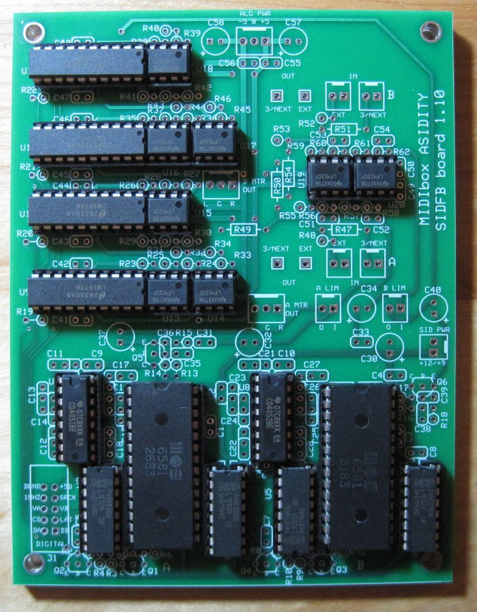
I just threw in the chips. /public/style_emoticons/default/smile.gif" alt=“smile.gif”> They’re not soldered yet–there are 650 holes in each board!
SIDFB Board Back

The back of the boards.
SIDFB Board Front
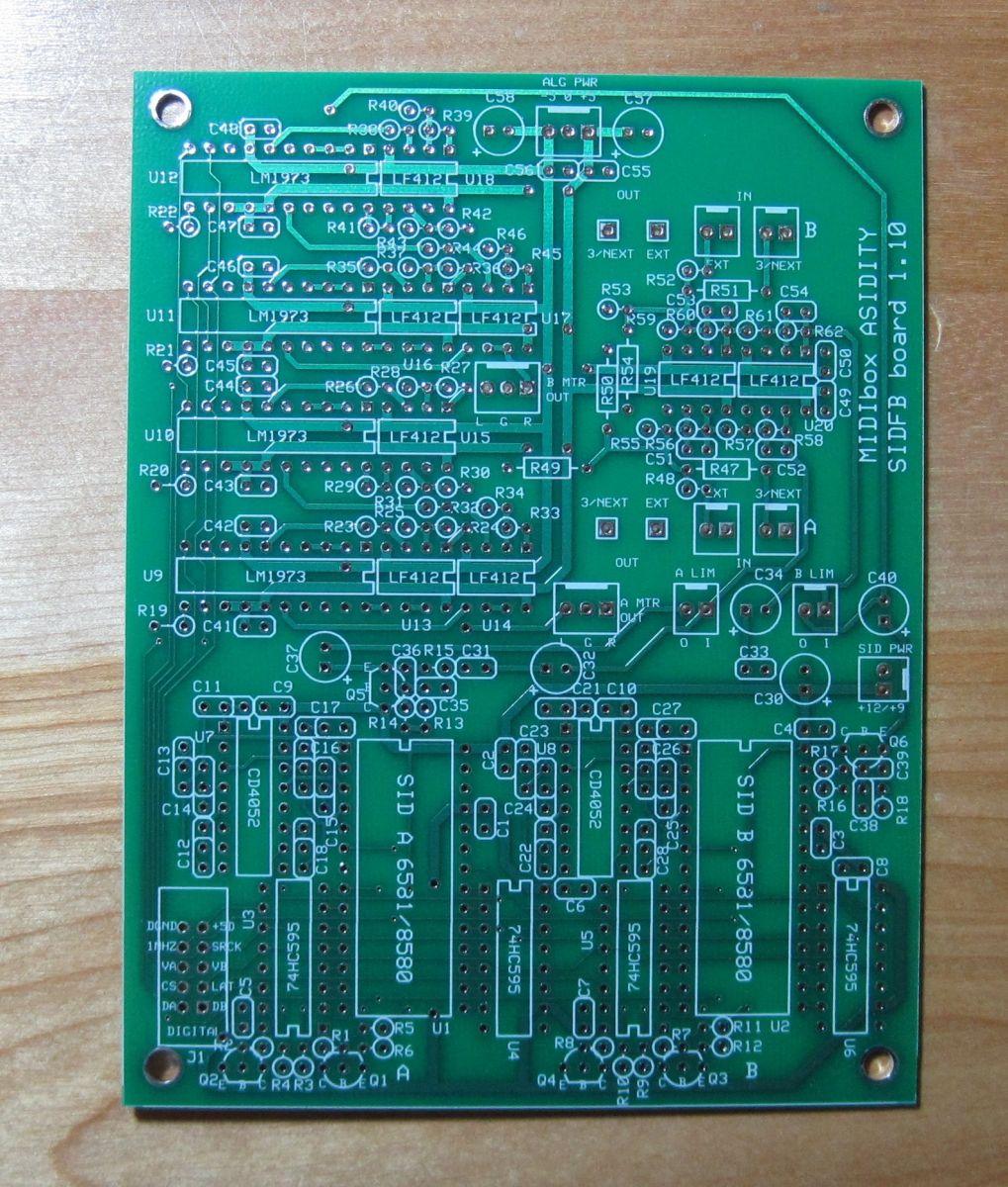
The circuit boards came in the mail today from ExpressPCB! Four custom MBHP_SIDFB module boards, each containing containing two SIDs, six channels of digitally controlled feedback and audio outputs per SID, and a CD4052-based circuit to switch between four pairs of filter capacitors.
MIDI interface board
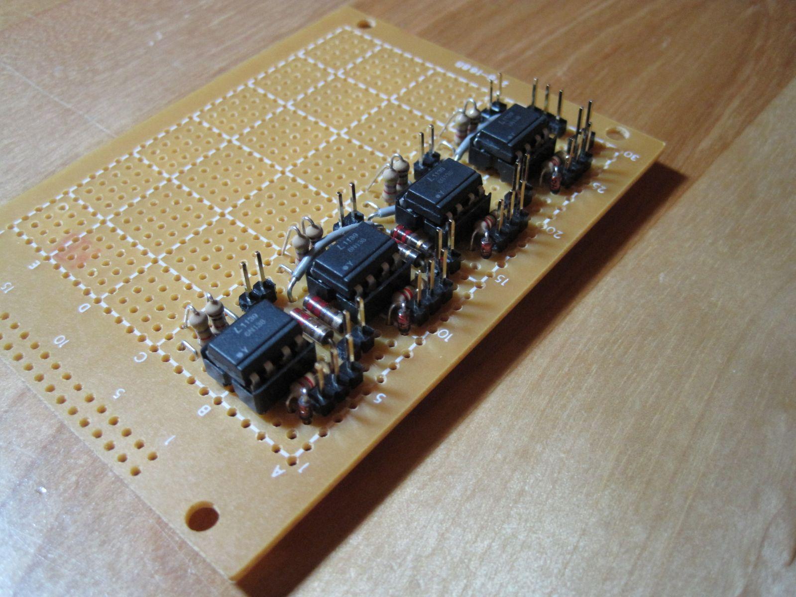
For the UART MIDI ports 3 and 4 on the SEQ and FP cores.
MIDI interface board

For the UART MIDI ports 3 and 4 on the SEQ and FP cores.
MIDIbox ASIDITY Front Panel Board Front
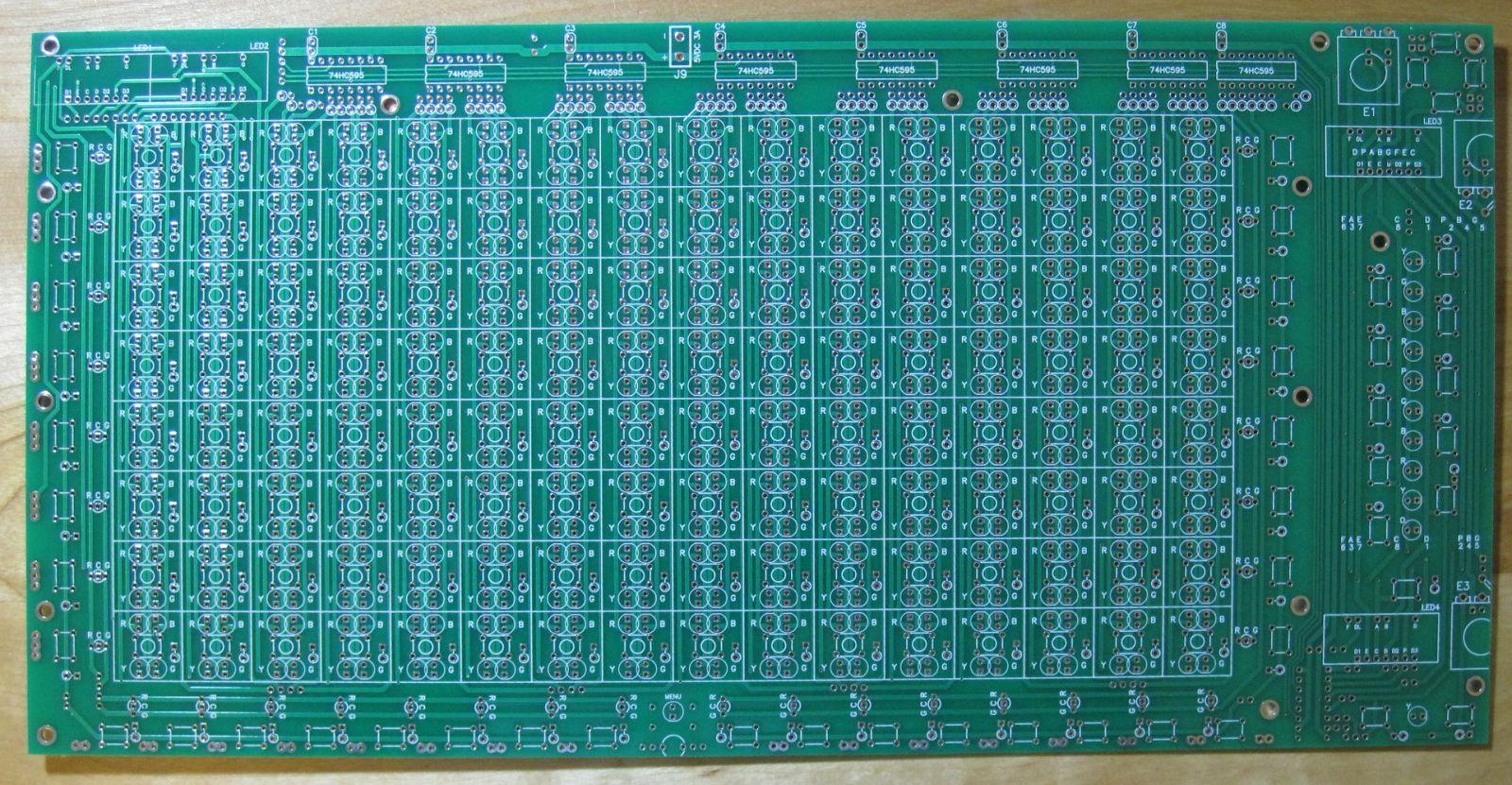
Our front panel board came today from Pad2Pad! It’s a little warped, though.

MIDIbox ASIDITY Front Panel Board Back
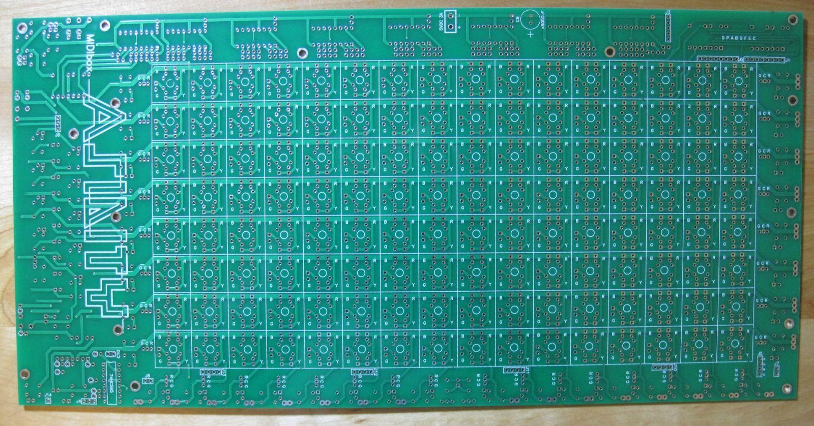
This is the side that will be seen when the synth is opened. Hence why the logo is on this side.

MIDIbox ASIDITY Front Panel Boards
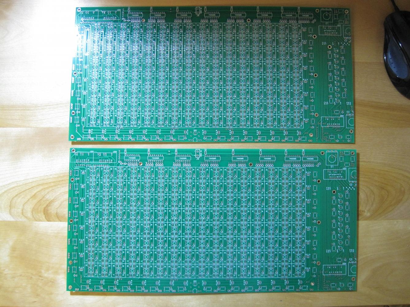
For some reason Pad2Pad sent TWO boards! We only ordered 1 (and only were charged for one), and it’s not that they had a minimum of two–in their editor, if we had ordered two, it would have been $70 more! Guess we have to build two of them now! Seriously, if someone is interested in building one of these, PM me and we’ll discuss things.
MIDIbox ASIDITY Logo
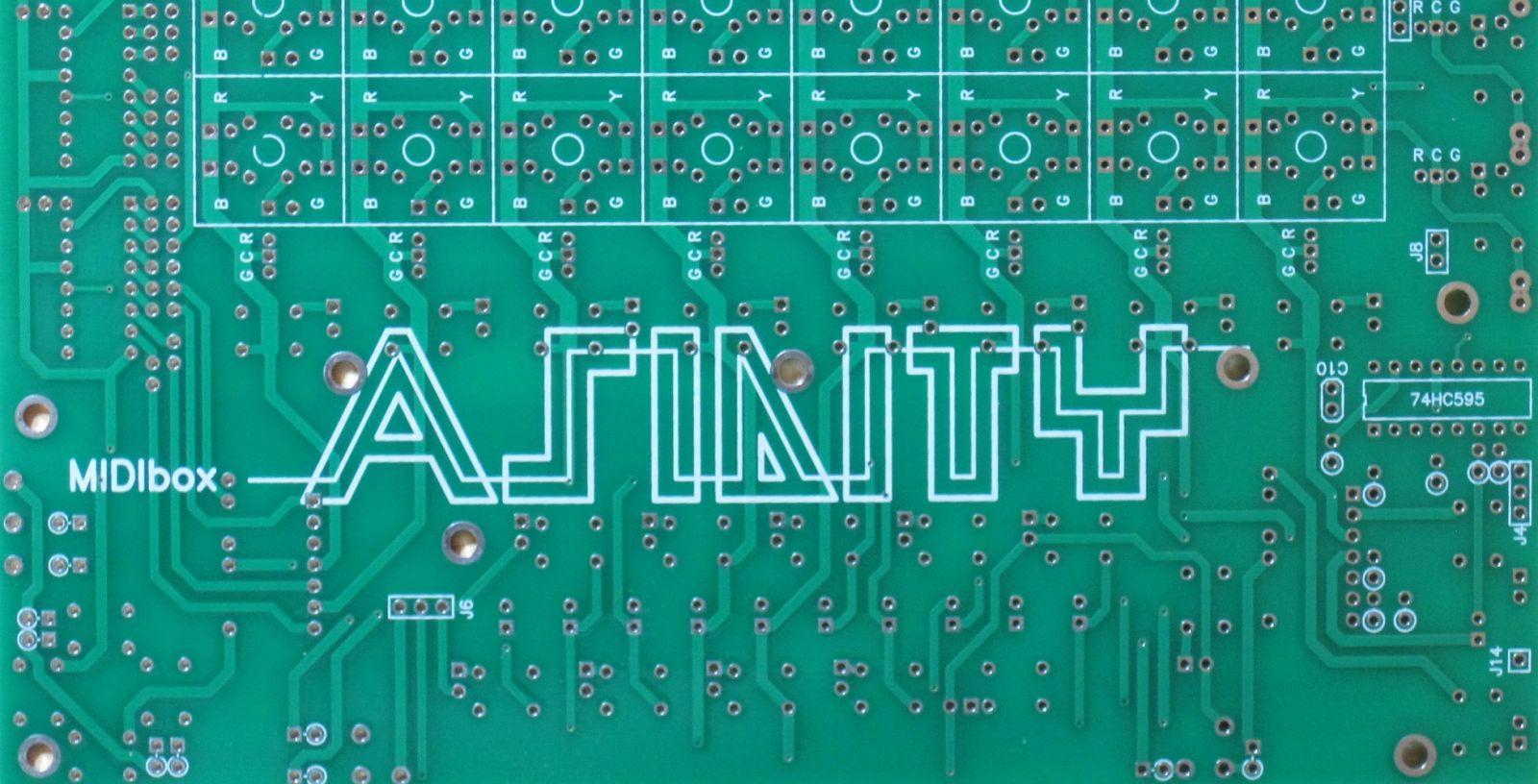
I specified in Pad2Pad’s design program that the outline letters would be on the “bottom unmask” layer, not bottom silkscreen, so that they would be brownish to contrast with the white.
But I guess they thought that was a mistake, and just switched the layer.
Complete SIDFB Module
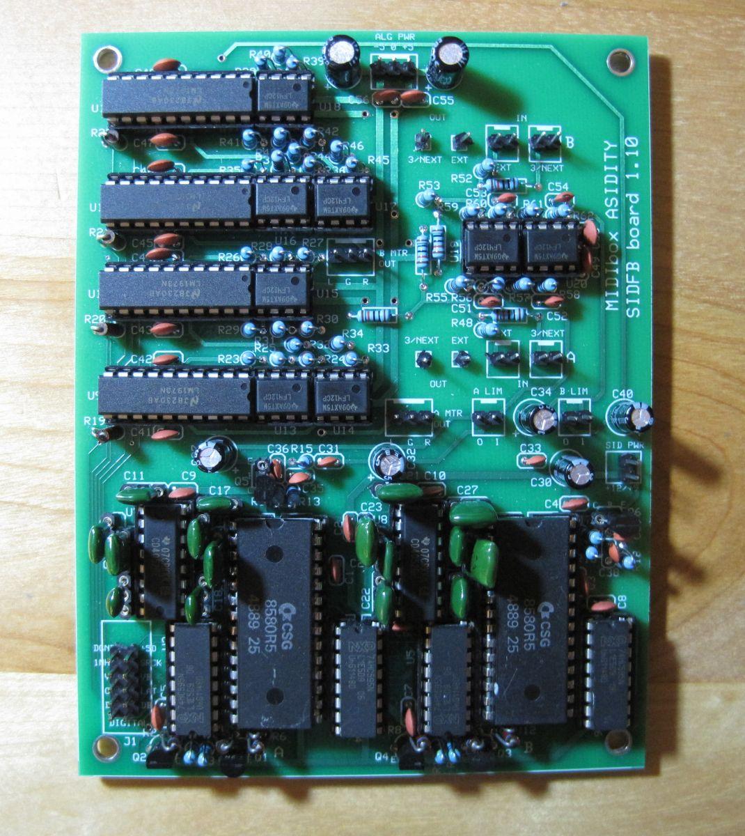
This is one of the four SIDFB module boards that will be in MIDIbox ASIDITY. It contains two SIDs and their shift registers; a CD4052-based digitally-controlled filter capacitor switching circuit, 4 pairs capacitors per SID; LM1973-based digitally-controlled audio attenuators controlling feedback to self, feedback to other SID on the board, feedback to SID on next board, external audio output, and master L and R outputs; and the mixer circuit for all the feedback inputs (and external input) to each SID. The boards are custom-manufactured.
The board contains twenty ICs, sixty-two resistors, fifty-six capacitors, six transistors, and fifteen connectors, for a total of 650 holes.
All SIDFB Modules Completed!
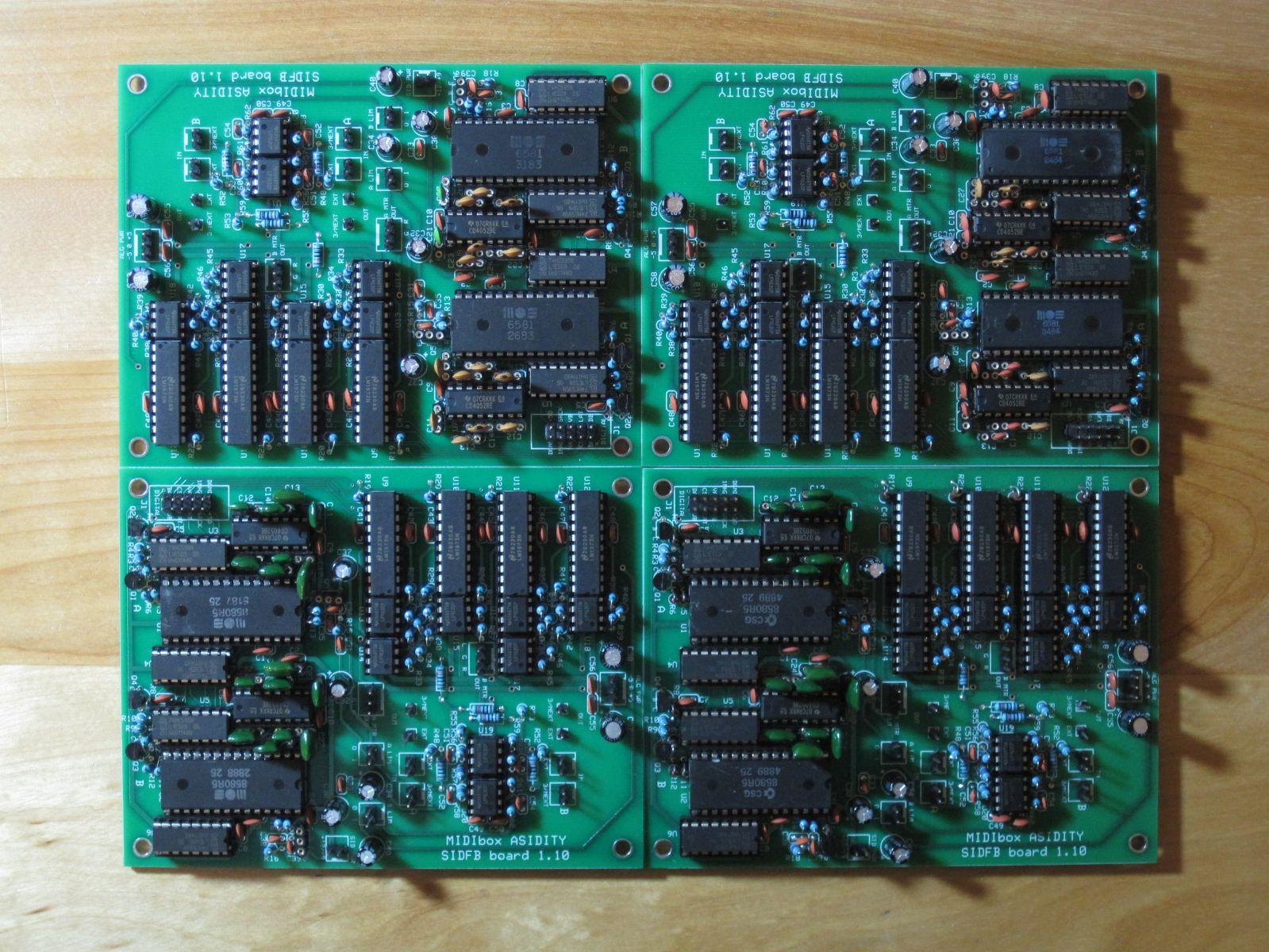
We finally finished soldering the SIDFB module boards! Each board contains two SIDs and their shift registers; a CD4052-based digitally-controlled filter capacitor switching circuit, 4 pairs capacitors per SID; LM1973-based digitally-controlled audio attenuators controlling feedback to self, feedback to other SID on the board, feedback to SID on next board, external audio output, and master L and R outputs; and the mixer circuit for all the feedback inputs (and external input) to each SID. The boards are custom-manufactured.
The total across all four boards: eighty ICs, 248 resistors, 224 capacitors, 24 transistors, and sixty connectors, for a total of 2600 soldered holes!
MIDIbox ASIDITY Case Partially Completed
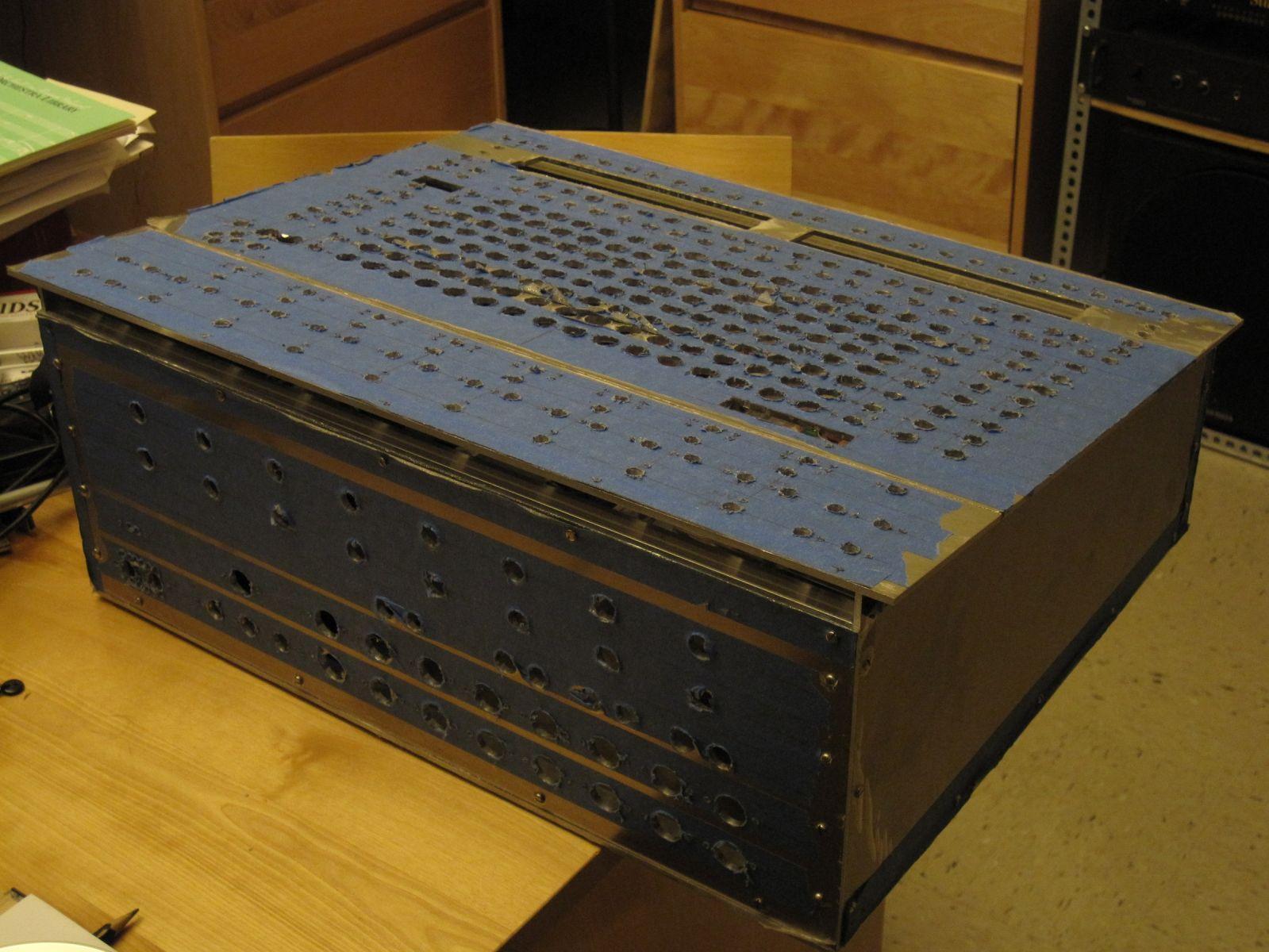
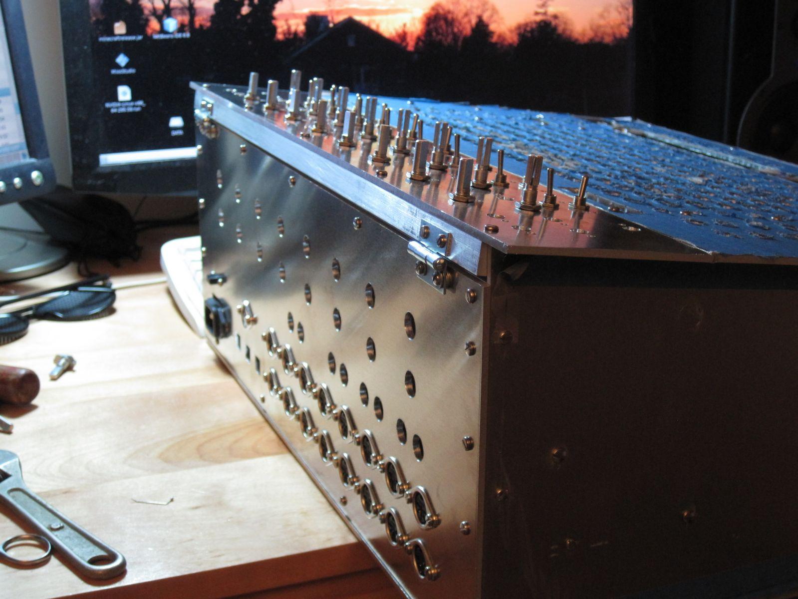
I had wanted to wait to show the case until it was all done, but after a day in the metal shop (back panel and top section of front panel), this photo was too good to pass up.

Case In Progress–Back Panel and Limiter Section
MIDIbox ASIDITY: Front Panel LEDs (x512!)
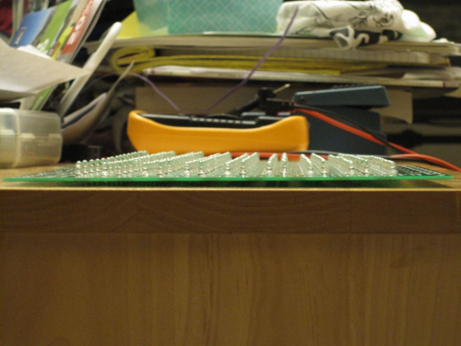
Red Yellow Green Blue, 8 rows x 16 cols!
MIDIbox ASIDITY Front Panel board almost complete!
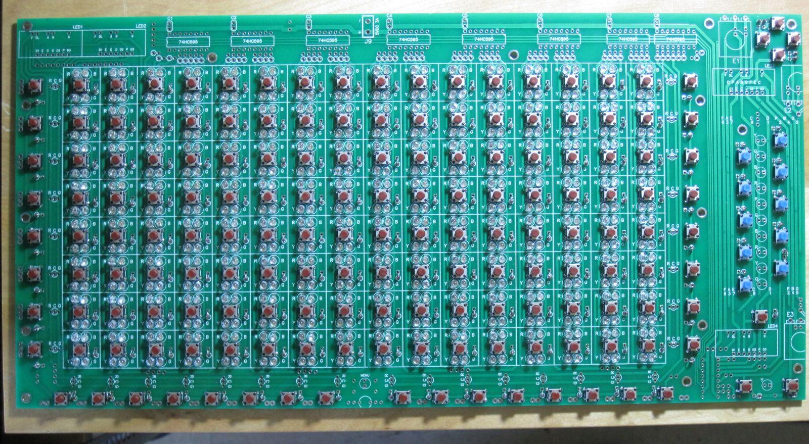
MIDIbox ASIDITY Front Panel Board Back View
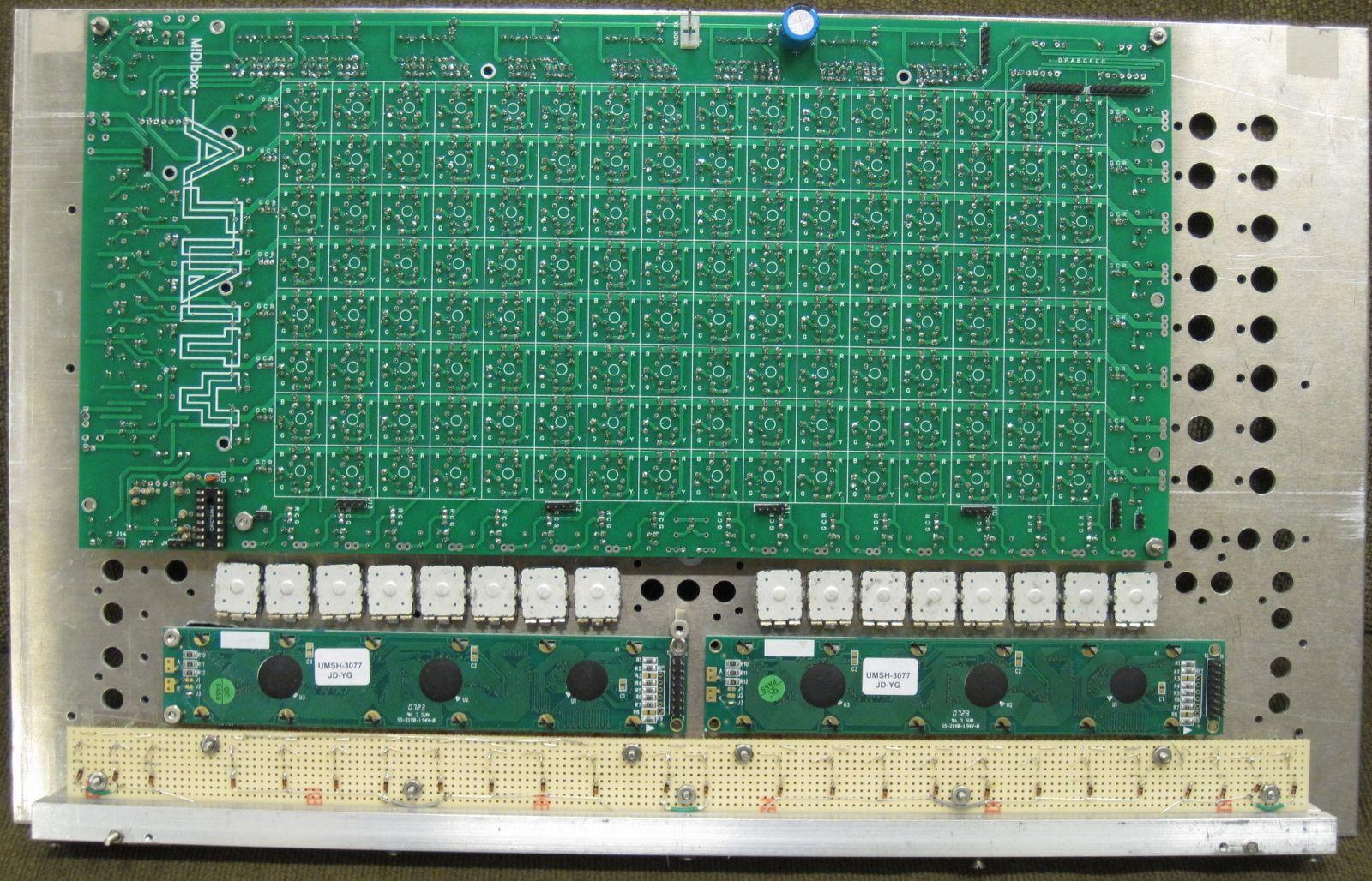
MIDIbox ASIDITY Front Panel
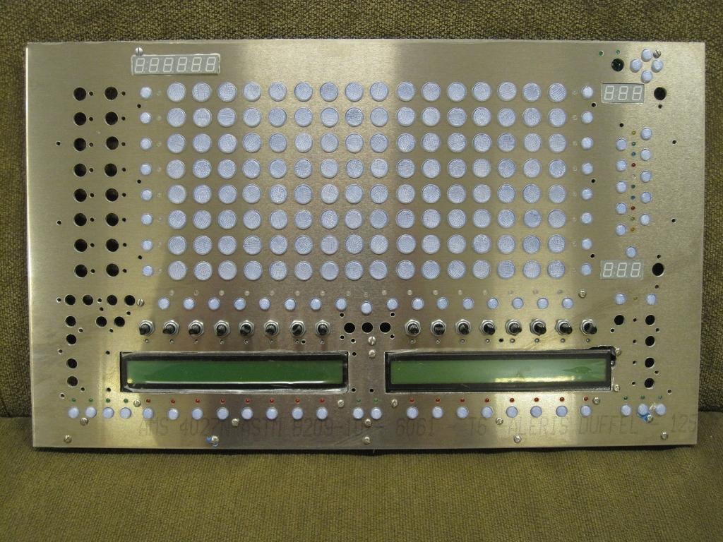
Partially assembled, of course.
MIDIbox ASIDITY Partially Assembled!
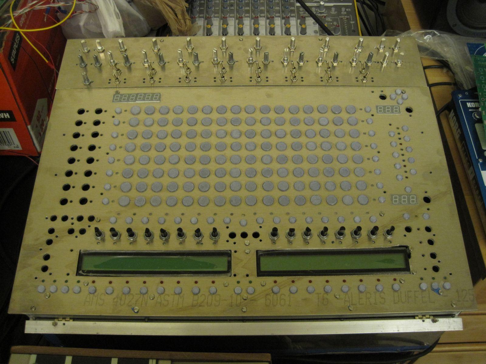
MIDIbox ASIDITY Front Panel Board Top Detail

Debugging MIDIbox ASIDITY
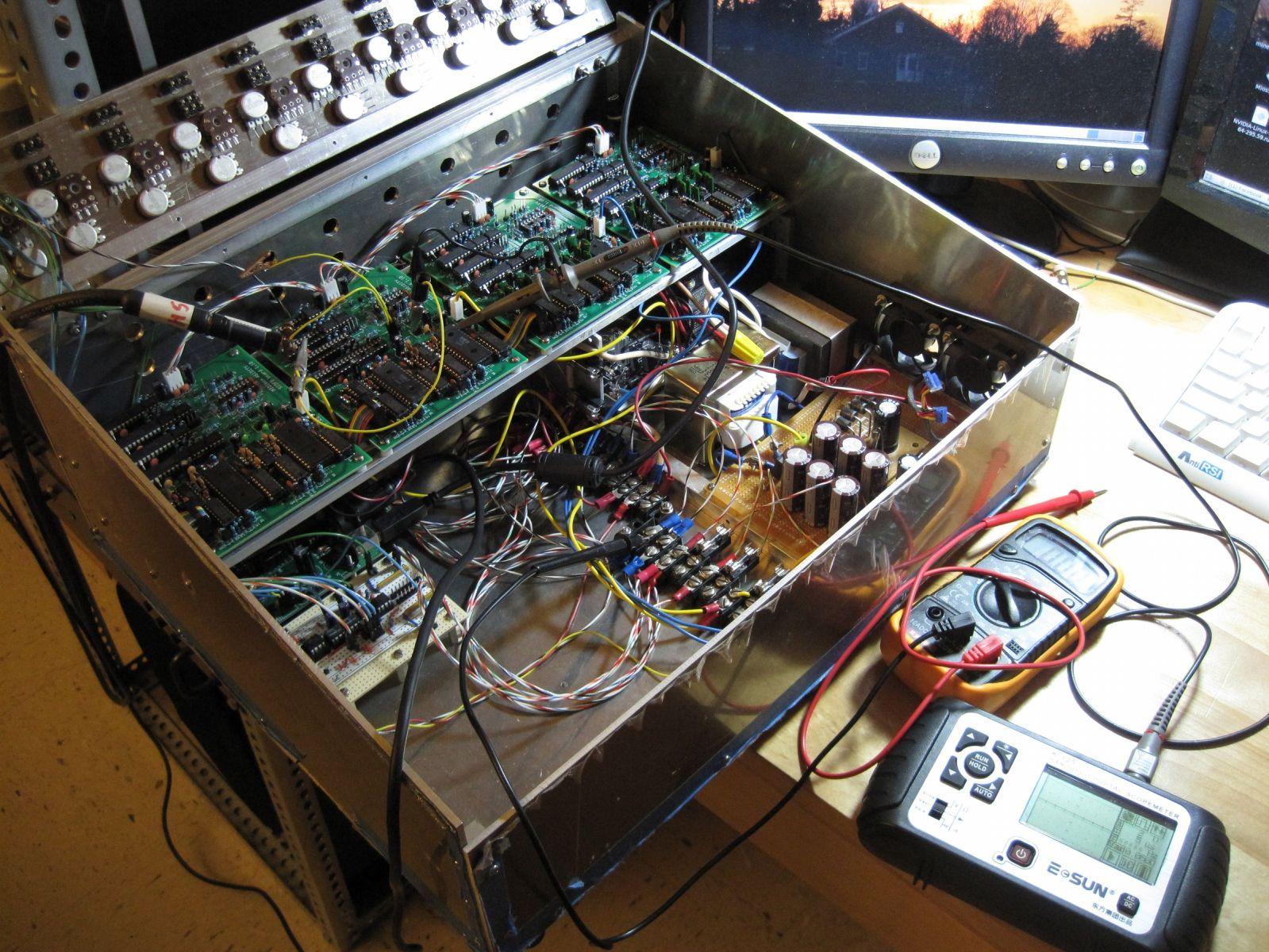
Two of four SID boards seem to work fine; two don’t make sound on the output of the SIDs. I’m on it!
MIDIbox ASIDITY Front Panel Board Complete
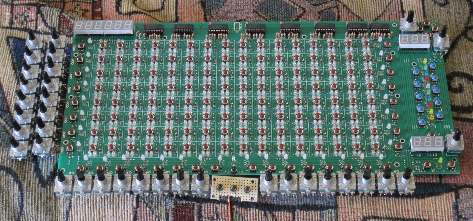
Can’t wait until it’s powered!
MIDIbox ASIDITY: Front Panel Back
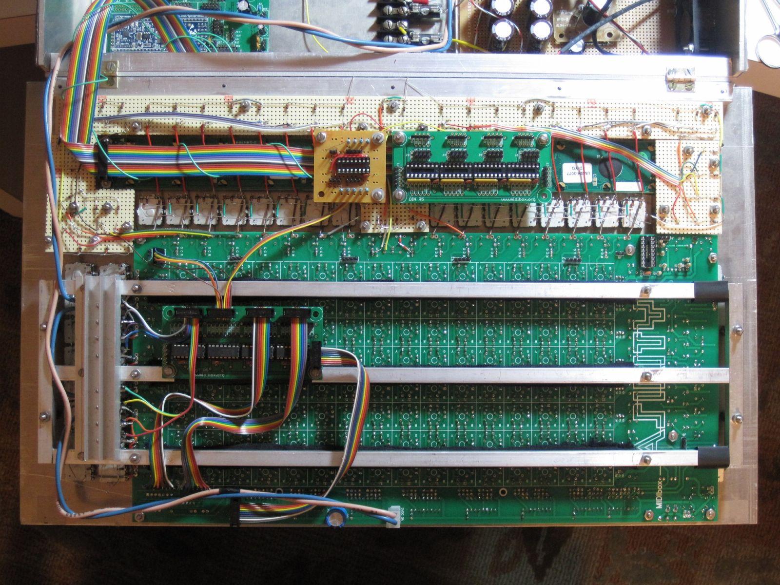
Only thing left is to connect some DIN wires, and then it should work. Of course, we all know how well things work the first time…
MIDIbox ASIDITY: Front Panel Complete!
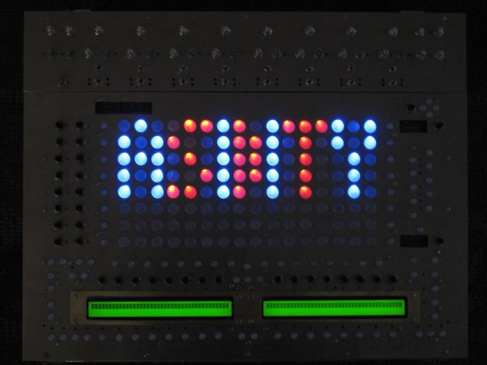
The front panel is finally working! It’s not entirely done–we have to get the LED displays and LCDs working, but the matrix works!
MIDIbox ASIDITY: 3 cores chatting (MBNET operational!)
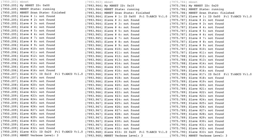
MIDIbox ASIDITY: 3 cores chatting (MBNET operational!)
Because the forum software won’t let me embed .png images…?
MIDIbox ASIDITY: LCDs Working
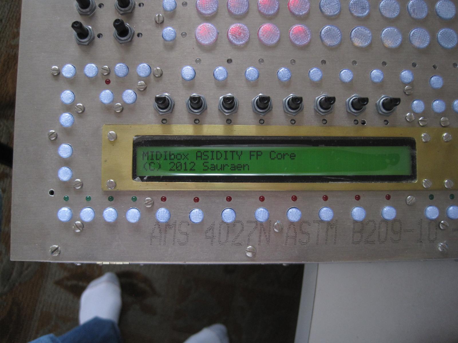
Shouldn’t have been that hard! (Bad connections in cheap IDC connector)
