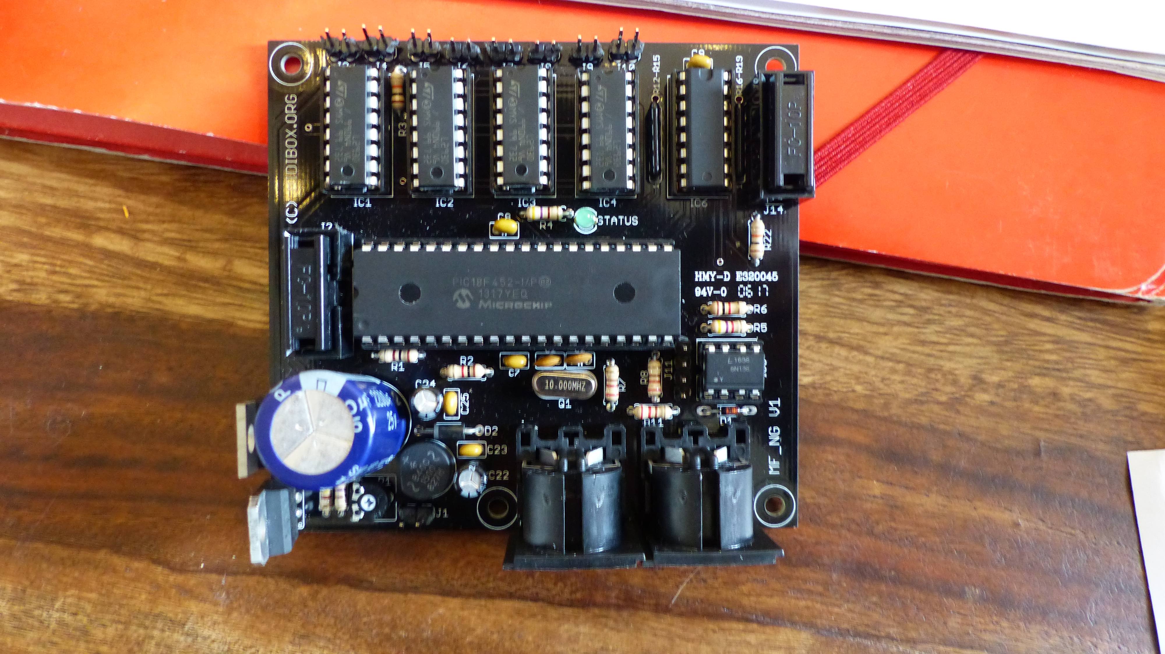
We bought a MF_NG Module kit to control motorized faders.
We soldered all components on the board. We assembled the pic18f452 with the PICkit2 on a breadboard. With the pickit2 v2.60 application, we charged on it "bootloader-> burner-> bootloader_v1_2b_pic18f452.hex ». The PIC was happy !
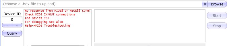
-> However, we don’t if we have to put the “midi -> mios8_v1_9h_pic18f452.hex” program with the picket 2.60 application or the the MIOS Studio application, we tested both but without success…
-> Also, once the pic18f452 is on the MF_NG board, MIOS Studio doesn’t recognize it, does it lack a little program with midi data or do we have a soldering problem ? We can’t verify it because others midi devices doesn’t seems to be recognize either, is it normal ?
Has anybody made this board before ? Can you explain precisely the steps to make it work ? We are a little bit lost in the ucapps website !!
re flash the bootloader onto pic using your pickit2
fit the pic into your mb_ng make sure you have polarity correct pin 1 to pin 1
once you have done that you need to connect a midi interface to your computer, and connect the in and out midi ports to the midi in and out on the mb_ng module.
MB_NG OUT----> COMPUTER MIDI INTERFACE IN
COMPUTER MIDI INTERFACE OUT----> MB_NG IN
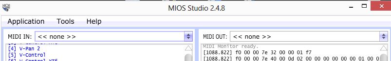
open Mios Studio
If you are using port 1 in and out on your midi interface then select the interface in the drop down menu for in and also for out
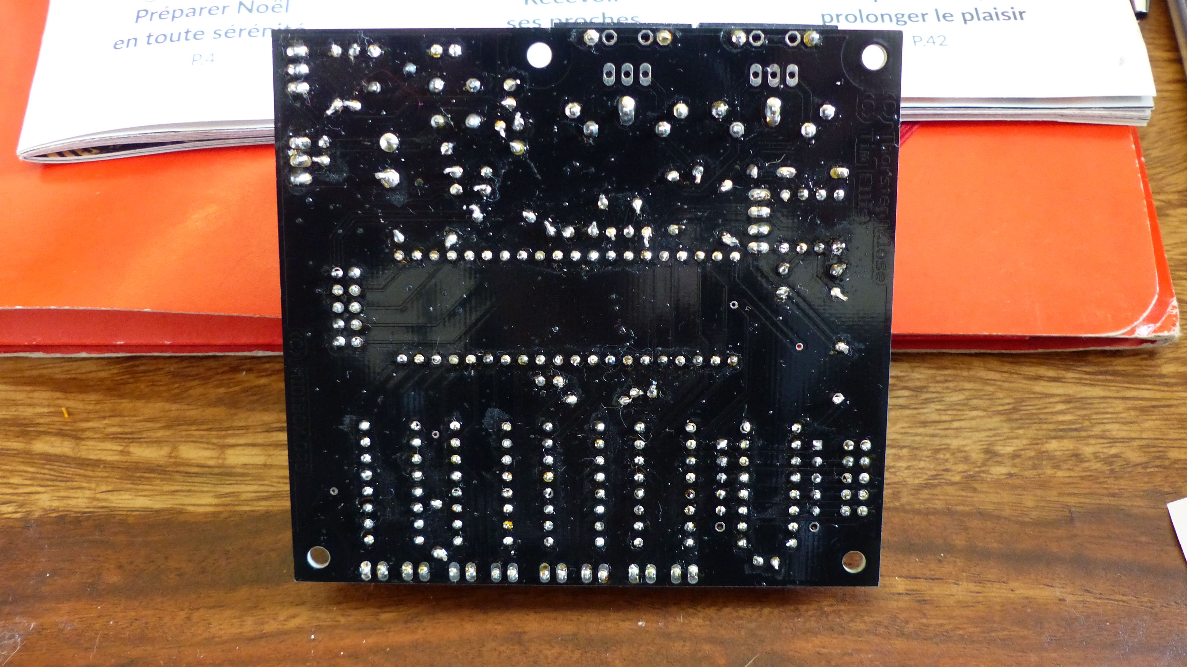
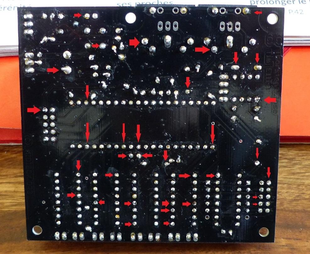
put pictures of yours up, the front and back of the board, make sure they are clear photos. The only way to know if anything isnt right is by photos,of the pcb both side.
are you sure have the right midi in and out selected in mios studio?
Thnigs to do
1: take good clear pictures of the pcb top and bottom
2: what midi interface are you using?
3: screenshot of mios studio with your midi interface connected and the in out ports shown setup.
4: try sending the hex file and take a screenshot of the mios studio window when this is done if it fails or not.
Then we can start looking at this for you.
I will dig out my board and gm5 and show you mine linked up this weekend.
I am looking at the soldering on the rear and I can see that some of the pic socket pins are not soldered correctly to the pads and some not at all it seems. reflow the lot on the back, just place your soldering iron on the pad and push some solder in gently to flow better.
Get some isopropyl alcohol from RS or Farnell etc to give the board a clean then.