I opened a separated forum section for discussions about the MIDIbox BLM, since this project is not tightly coupled with the MIDIbox SEQ project, but can also be used standalone.
Schematics:
- mbhp_blm_scalar.pdf the “BLM_SCALAR” module
- mbhp_blm_scalar_module_interconnections.pdf interconnection diagram. 5 x BLM_SCALAR modules are required for a complete BLM16x16+X
- mbhp_blm_map.pdf the mapping between BLM_SCALAR and Buttons/Duo-LEDs.
I’m not planning to layout the PCBs by myself, but volunteers already evinced to help out! ![]()
Just start to coordinate your efforts here.
Some input from my side:
as you know I created the BLM16x16+X on veroboards ()
For me this was less time consuming than layouting and ordering PCBs, especially since at the time where I started this project it wasn’t clear if the SRIO hardware will work stable - I used tricks that I never tried before to reduce the chip count.
With the prototype I’ve proven that the concept is working, so that I can release the schematics for layout.
If somebody really plans to build the circuit on verboard like me instead of waiting for the PCBs, be warned that you need some soldering experience, a lot of time and especially patience!
It took me ca. 40 hours to complete the BLM16x16+X on verobards.
It was hard work and I would never do this again! ![]()
With PCBs I expect only ca. 15 hours work, a more stable construction, and less risk for wiring errors (-> newbie friendly).
My costs so far (all parts ordered at Reichelt):
LED 5 RG-3 Duo-LED, 5mm, 3pin, rot / grün 300 45,00 Euro TASTER 3301B Kurzhubtaster 6x6mm, Höhe: 9,5mm, 12V 300 30,00 Euro 1N 4148 Planar Epitaxial Schaltdiode, DO35, 1 300 6,00 Euro
To speed up the wiring I used “verowire” (german: “Fädeldraht”), and I used 7 x “H25PR200” veroboards which won’t be required for a PCB based solution, therefore they are not listed in the list above.
I strongly recommend you to order 300 LEDs/Buttons/Diodes as well although only 289 are used.
E.g., at my order Reichelt only sent me 296 LEDs instead of 300 - good that these were spares!
I had the remaining components for the 5 BLM_SCALAR modules + 1 PIC based MBHP_CORE already in my “personal stock”. If you are interested in the part numbers you will find the references at the MBHP_DIN and MBHP_DOUT page.
Layout suggestions:
in the last months I got some mails about how a BLM layout could look like, and this only showed me that it will be very hard to find a universal solution.
E.g., somebody proposed to prepare the layout for different button footprints.
My comment: due to the increased amount of drill holes this will lead to much higher costs for everybody.
Somebody else proposed to use RGB LEDs instead of Duo-LEDs, since they are cheap at EBay
My comment: this will increase the costs for everybody again, and it will be hard to find the same LEDs at such a high amount.
E.g., consider only 30 people would like to join the PCB order - they would have to find ca. 8700 RGB LEDs from the same seller, or some of the people would have to buy more expensive RGB LEDs from a regular electronic shop.
Another point that needs to be considered: for the BLM16x16+X I already chained 15 74HC595, MIOS8 supports 16 DOUT shift registers maximum. Increasing the amount of DOUT registers to control the blue LEDs will lead to difficult software changes.
Third point: RGB LEDs draw much more current, especially more than Red/Green LEDs. Blue LEDs probably require additional transistors (or ICs) as source driver.
The additional 74HC595 and these source drivers will require a different BLM_SCALAR module - again it doesn’t make sense to bring this into an universal layout that is intended for my original project.
I’m sure that most people will be happy about a cost efficient solution with Red/Green colour LEDs (like me).
Buttons: this will also become a difficult topic.
I will use these ones:<___base_url___>/index.php?/topic/13532-inexpensive-solution-for-illuminated-buttons/&do=embed
But I’m not sure if this construction will be stable enough.
A better solution could be the usage of the same buttons and caps that where used on Wilba’s MBSEQ frontpanel.
Partitioning the PCBs:
the SRIO and BLM circuit has already been separated. The SRIO boards are stacked under the BLM board.
It has to be considered if a huge BLM board is better than splitting the circuit into two or three parts (think also about the reduced shipping costs…)
For the BLM_SCALAR boards I recommend separate modules for each 16x4 matrix, because it is too difficult to plug the board into more than 2 large dual pin header sockets.
Note that this approach would also allow you to use the same BLM_SCALAR boards for different BLM board designs!
Matrix routing:
can be changed if really required.
The firmware has to be adapted accordingly (changes are difficult for somebody who never worked with forward/backward matrix transformations before, see main.c)
Therefore changes in the routing are only recommended for people with software programming skills.
Additional features:
I will add 6 faders to my BLM16x16+X, because I find it important to get the possibility for manual sound changes with one hand, while sequences are changed with the other hand (therefore it’s better to have the close to the matrix).
The firmware is prepared for up to 8 pots/faders.
More informations/suggestions on request.
However, my hope is that this will become a community project where experienced people will help out and where I don’t need to support you that much!
I could be interested to join the PCB/kit bulk order as well! ![]()
/Update Oct-2015: after 5 years finally we got a kit created by Latigid On!
->
/Update Jan-2016: new firmware blm_scalar_v1_1 can be downloaded from http://www.ucapps.de/mios_download.html
It contains prebuilt hex files for various hardware configurations:
o project_without_ain.hex -> without AIN enabled (use this if J5 pins not connected to ground)
o project_with_4_mapped_ains.hex -> for Latigid On’s BLM PCB layout, only 4 faders used
o project_with_4_unmapped_ains.hex -> AIN pins are mapped 1:1
o project_with_8_mapped_ains.hex -> for Latigid On’s BLM PCB layout if 4 faders + 4 extension AINs are used
o project_with_8_unmapped_ains.hex -> AIN pins are mapped 1:1
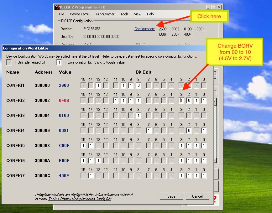
/Update Jan-2016: if you are using a PIC18F452, it’s required to change the PIC device configuration while flashing the bootloader: the brown out reset level has to be changed from 4.5V to 2.7V as shown in this picture:
Otherwise PIC could be reset sporadically (depending on the number of enabled LEDs) because the voltage level could fall below 4.5V!
This change is only required for PIC18F452, other pics (such as PIC18F4620 and PIC18F4685 will work w/o this change).
Unfortunately this change can only be done with a PIC programmer. Please contact me for the case that you don’t own a PIC programmer. I could send you a replacement PIC18F452
Alternatively use a PIC18F4620 or PIC18F4685 if you own one
Best Regards, Thorsten.