Once I know that the PCB is working, than I’ll have to change a few things in the SeqV4 and MIOS32 software:
For a the dogm LCD I’ll have to change the SEQ_LCD_PrintString commands, mostly in the SEQ_UI… files. Hopefully with this display (8X21 characters with small font) I’ll be able to modify most of the menupages with adding
SEQ_LCD_CursorSet(0, 2);
SEQ_LCD_PrintString…
SEQ_LCD_CursorSet(0, 3);
SEQ_LCD_PrintString…
SEQ_LCD_CursorSet(0, 4);
SEQ_LCD_PrintString…
…
I’ll have to add some code to make sure that the encoder next-to the BMP 3X 7segment will always change the BMP, no matter what menu the sequencer is in.
I am not using 16 encoders so I will have to change and add code for one encoder to move “left” and “right” to the different fields that can be changed in the current view or menupage on the display. And for the other encoder to be able to change the value of the selected field.
Could someone also help me out with the questions below:
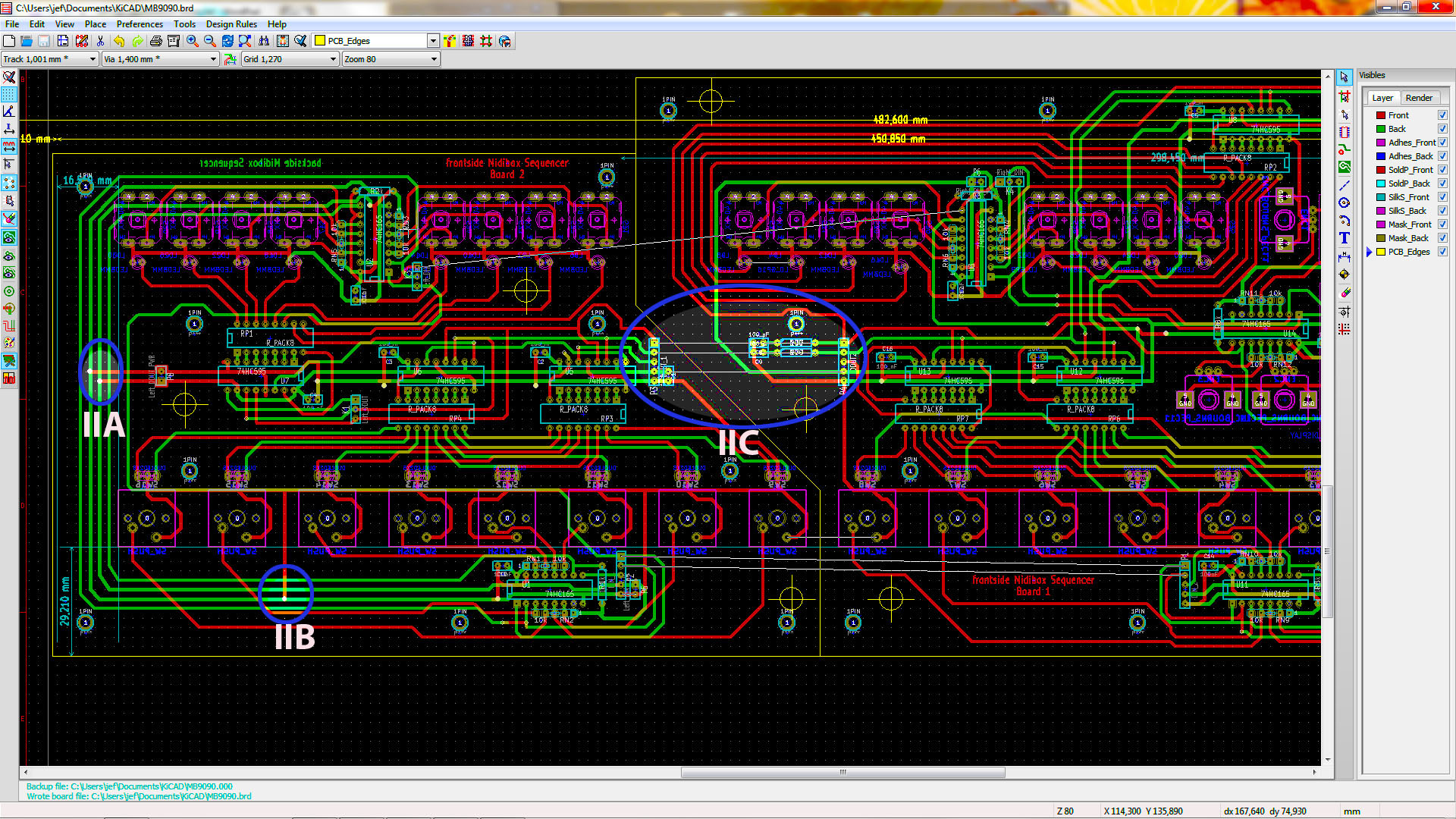
MB9090 board1.jpg :
IA: Is this the correct order to connect the encoders with the 74hc165 (see also the INPUT schematics)?
MB9090 board2.jpg:
IIA: Is it ok to interconnect Ground and power of the DIN and DOUT circuit like I did?
IIB: same question as IIA
IIC: this is a KiCAD question: I don’t know how I can put in the schematic or the board that these are
connected through the connectors and wires. I have put a different type of labels in the input schematic than the
ones in the output schematic but the result is the same :sad:
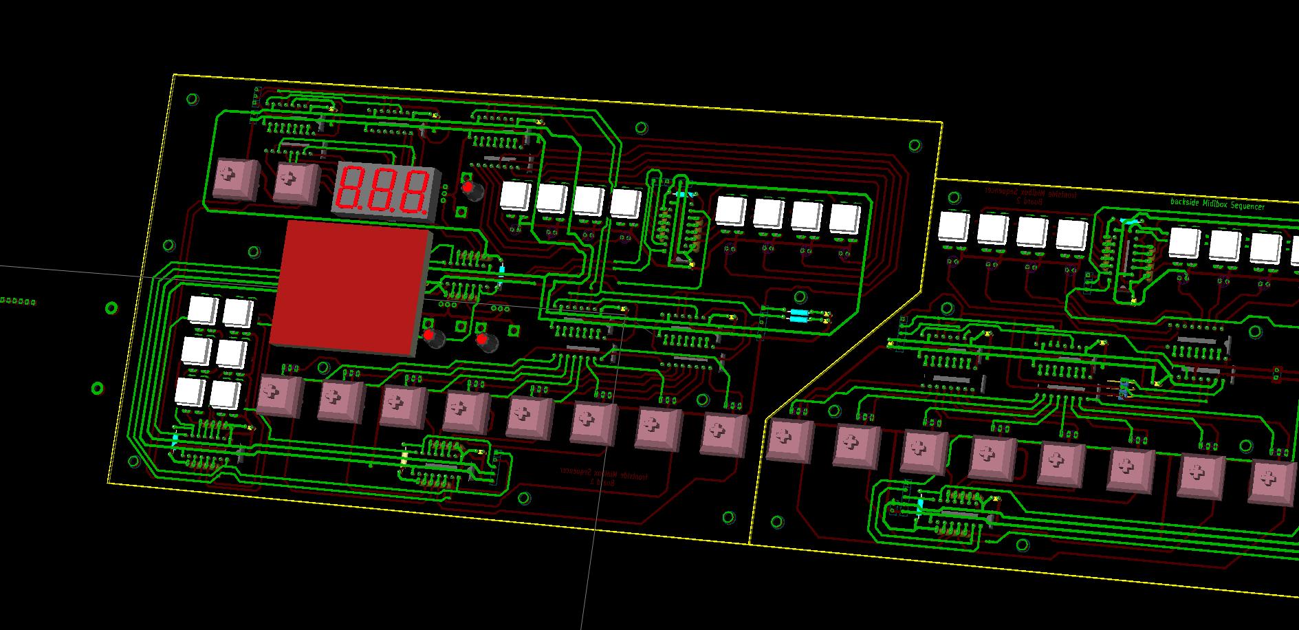
Just wanted to share a 3d pic of my MB9090 SeqV4 (Roland 909 clone). :sorcerer:
And I would like to thank all of you that have already helped me: thanks .
Hey, pcbatterij,
anything new on this topic? I’m just about to start soldering 9090 boards tonight and this one looks quite interesting. Any progress on the sequencer prototype built?
I am also building a website because there are quit a few restrictions on the blogsite, check the website on: http://users.telenet.be/MB909/
The website is still under construction but I am updating as fast as I can. I can do this because I am still waiting for the parts from Mouser.
I will start soldering the LPC board tomorrow with the parts that I got from Reichelt.
The 9090 is working fine!!! I love the drum machine. I only have to replace one potmeter because this is the one that is causing a hum from time to time.
I don’t have a laser printer and the copies from the local copy center didn’t work to make the PCB’s for the sequencer.
If you have any questions about the 9090 parts or making the boards, don’t hesitate to contact me.
Ah, sorry, refreshing the blog regularly but I missed the last post from Nov 7th
I will start soldering the LPC board tomorrow with the parts that I got from Reichelt.
I soldered two during the last day, I had no issues, was finished in 2 hrs and it worked right after the power-of, I only had slight issues while getting familiar to LPCXpresso, but I succeeded there as well…
The 9090 is working fine!!! I love the drum machine. I only have to replace one potmeter because this is the one that is causing a hum from time to time.
Can’t wait to have it finished I started soldering diodes yesternight, can’t really decide if I should solder by sections or by components size. If I get some silicone glue it’d be better to solder by sections but since I don’t have the glue yet holding the small components while soldering them might prove a bit difficult, I’d say… Nevertheless, I’ll figure it out somehow
I started with the power than did the bass drum and the midi section. As soon is I tested the bass and knew the midi and power worked, I then did a mix of soldering by component size and by section.
Can’t wait to have it finished I started soldering diodes yesternight, can’t really decide if I should solder by sections or by components size. If I get some silicone glue it’d be better to solder by sections but since I don’t have the glue yet holding the small components while soldering them might prove a bit difficult, I’d say… Nevertheless, I’ll figure it out somehow
When I did mine (with the help from friends - there were too many components to keep track of!) I first placed *all* the diodes on on PCB. Then I went on to all the resistors, then caps on that PCB one section at a time. There are still no completed circuits to speak of. I still checked for shorts between Vcc and ground each step just to satisfy my paranoia. Also, I measured all the passives before soldering them in place. Add all the IC sockets and pin headers so that all is done by height. There are still no completed circuits to speak of, but measure just to be safe. Add transistors. Measure. Still OK? Add ICs section by section. Check! I did the MCU and MIDI first so that I could check that part and get triggers and velo for the voices. I first faked triggers to each drum voice, then I went with MIDI notes. Last I did the outputs for listening and the pots. Before then I just watched the drum sounds on the oscilloscope - I recognize those sounds just by looking at the waveforms… Nerd alert! :geek:
Still, there were a couple of errors that got by me anyway - the 3080 in the clap was broken. Replace and it started to sound like a proper clap. Then, there was an error with the crash or something - a R2R DAC resistor got mixed up so it had the wrong value. Interestingly enough no other resistor was off so there was no simple component swap. Phew! It did sound very crappy and nasty though. Distortion from hell idea…
Lots of board real estate was wasted by the toms - I did them just for completeness - it’s unlikely they’ll ever see much use unless I want to cover the Miami Vice theme by Jan Hammer or any other 80’s pop. I would have gone with moar claps or any of the other, fun voices instead.
 .
.