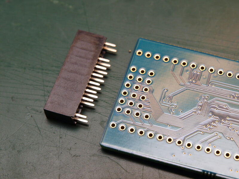
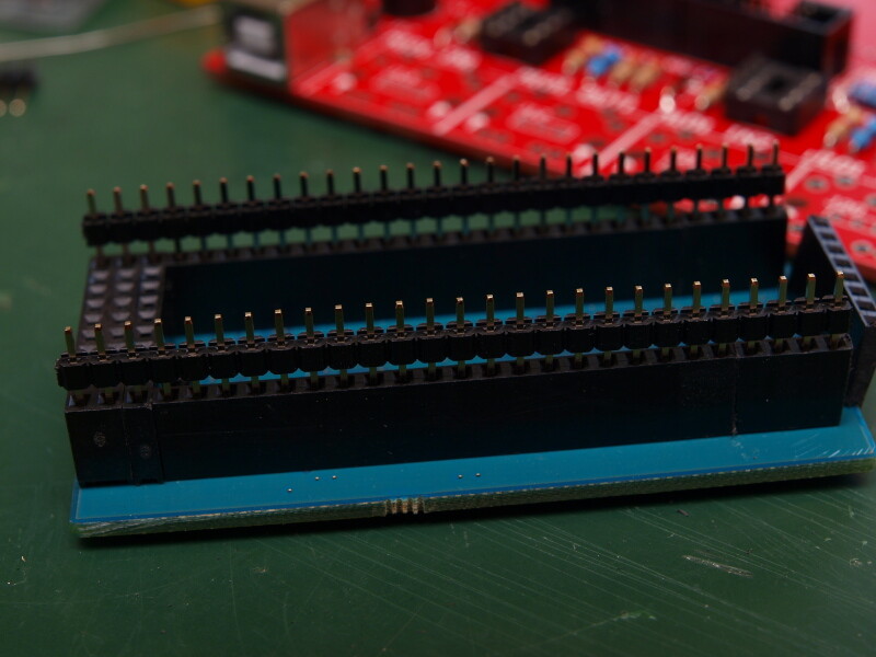
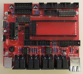
I have just completed my LPCXPRESSO board sitting on top of the new MBHP_CORE_LPC17 base board. As I wanted it to be removable - the LPCXPRESSO will be used on more than one base PCB - I used male and female headers. Female headers are attached to the LPCXPRESSO, just because they are the more expensive ones, and I plan to circulate one LPCXPRESSO board between a number of different LPC17 base boards.
It is a little tricky to align the sockets properly, as the female SIL sockets you can get from Reichelt are slightly too long. It means you cannot simply “chain” them, but some material has to be removed from the short side in order to keep the grid.
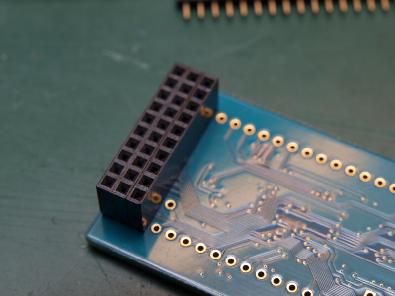
Also, I made sure that male and female headers sit perpendicular (horizontal vs. vertical alignment in the fotos) to each other, so that the hole assembly cannot fall apart. Also, this way you make sure that the spacing is correct in both dimensions.
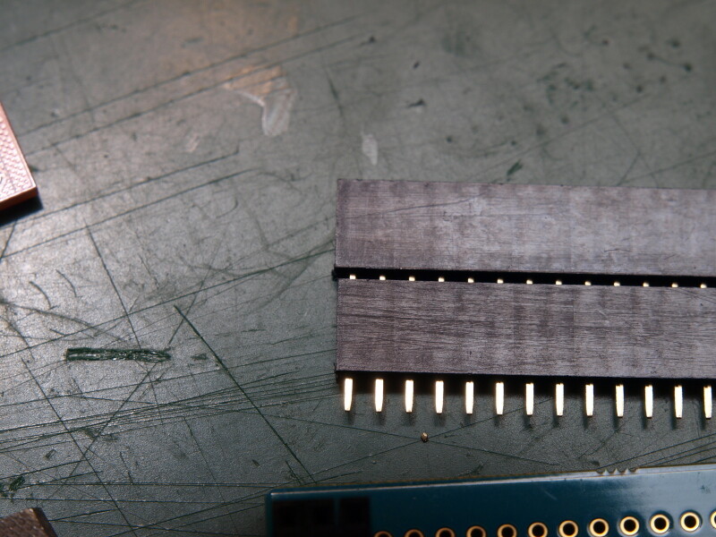
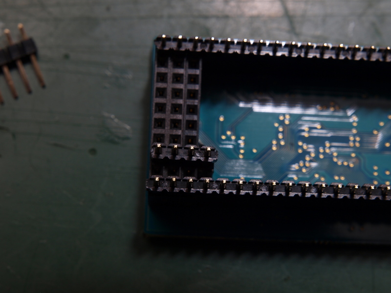
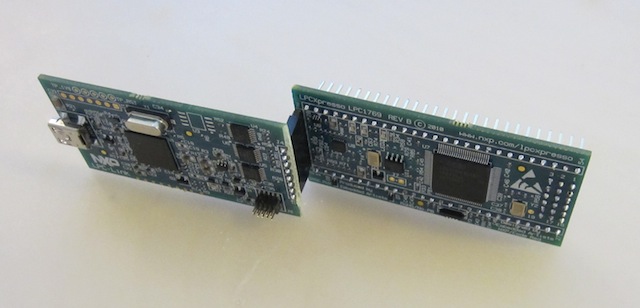
Here the two boards have been separated again: you can see how nicely the grid is kept, although it consists of many different (separate) headers. I will use the exact same LPCXPRESSO board again when I prepare the next LPC17 base board!
I will add a link from the MBHP_CORE_LPC17 page to this posting under the topic “strongly recommended, but not required if you are sure what you are doing”.
In long term - if kits will ever be provided for this module or for derivatives - matching sockets (which don’t need the file work to shorten the sockets) could be sourced and added to the kit.
Another note: personally I would prefer to use female sockets on the MBHP_CORE_LPC17 module, since this is compatible to the Base Board provided by Embedded Artists, and since it’s more likely that I would replace the LPCXPRESSO module by a pin compatible module in future, than circulating it between different base boards.
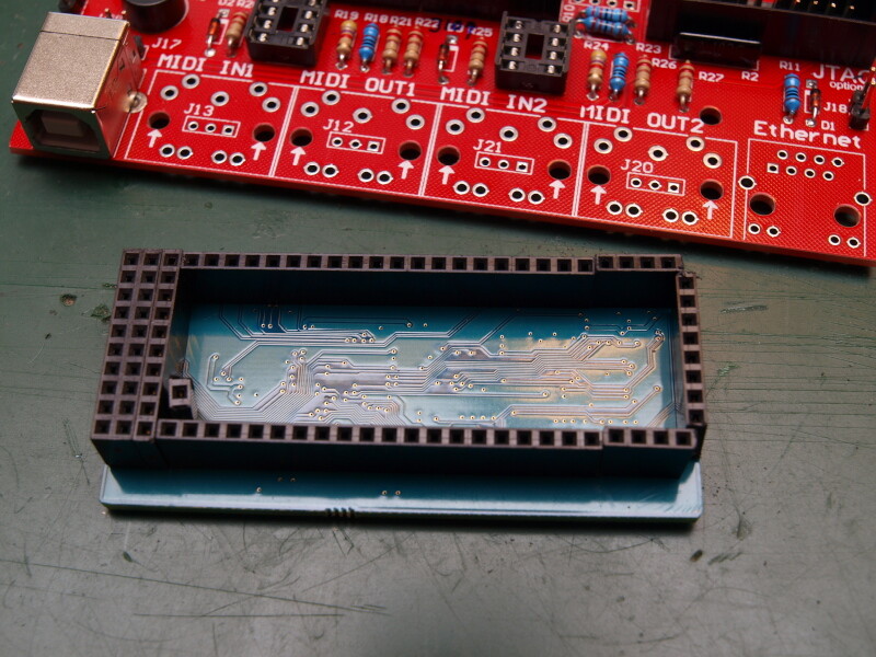
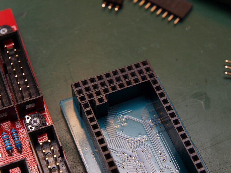
Now I’ve stuffed a module with (female) sockets as well - after I’ve shortened the Reichelt sockets with a file they fit.
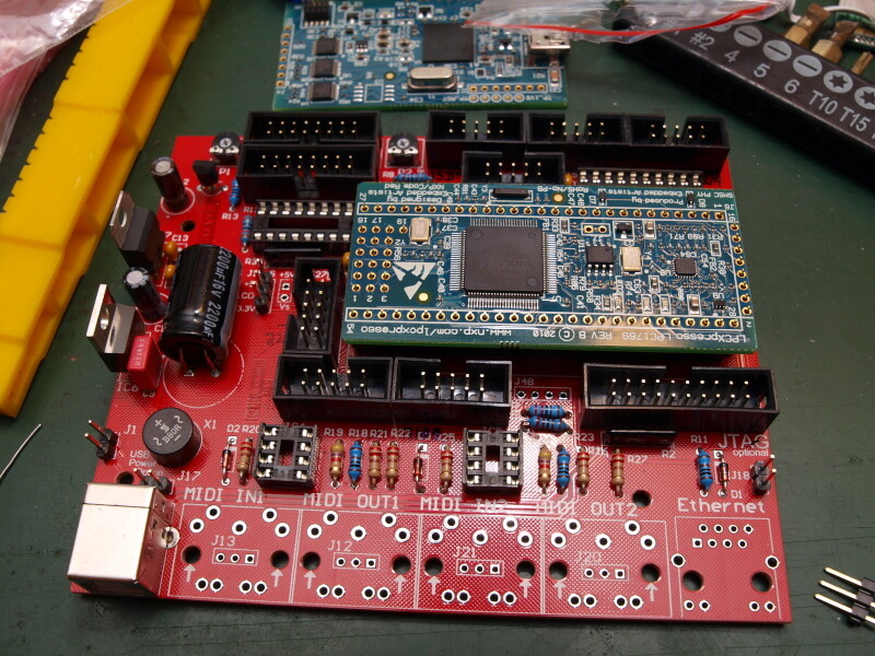
Note how I’ve soldered the male headers to the LPC-Link board.
For users who don’t own a common JTAG interface, it’s recommended to solder them upwards so that the LPC Link can be connected this way:
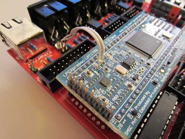
Here another picture which shows that the ethernet LEDs have to be connected via two wires to J26, since the LPCXPRESSO module doesn’t provide dedicated pins for the two Ethernet Socket LEDs.
(Ilmenator: J26 doesn’t exist on the first prototype board)
Is it possible to connect/use the LPCLINK module while the LPCXPRESSO is connected to the base board?
Yes!
You even don’t have to take care if the LPCXPRESSO is powered through the MBHP_CORE_LPC17 module (means for example: LPC-Link and MBHP_CORE_LPC17 USB plugs connected to a computer) since there are protection diodes.