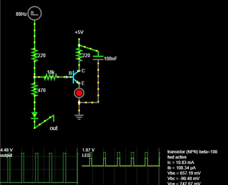
I know this topic has been raised before, and I’ve read through some of those threads, but I haven’t found a definite answer and couldn’t find Altitude’s files on the wiki to use as reference. I saw that Hex Inverter’s MIDI2CV was mentioned as an example of a usable LED driver. The specs of the MIDI2CV quote a gate output of 0-5V. Some research proved that this is a common method of LED driving, and of course that there is plenty of debate about which method is best.
I have designed an 8-output board based on that, but I had D0-D7 reversed on my first batch. Before I order new boards, and as I’m not an EE, I figure it’s best to confess my ignorance and get some input on the circuit from some other MBHP builders here before I have these fabricated. Below is a schematic of the circuit, one instance per output. The 220Rs are already installed on my DOUT board, so I’ve included them in the sketch. The 33k is based on the original circuit, but I changed his 1K at the collector to 150R (based on a basic LED-resistor calculation) and plan to use some of the 220s I have left over instead…but this doesn’t account for other variables (the 33k, the 3904) because I honestly don’t understand the equations.
Here’s the datasheet for the 3904 http://www.mouser.com/ds/2/308/2N3904-1118515.pdf
I tried this circuit in a simulator with various resistor values. I was attempting to tune it for Vbe saturation per someone’s advice, but I don’t know what I’m doing. If I change R2 to 18K, I get the following results, but I’m not sure that matches my targets from the datasheet (again, I don’t pretend to have a grasp of this yet).
What are most people doing for their gate/trig/clock outs? Sockets wired directly to J3-6 on DOUT with no LED or output protection? Am I totally off track?
Thanks in advance for any advice!