GLCD for Sample controller project

Hello,

Sorry I bother again, but I had a question about a recent project I’m working on.

I want to create a “sample controller” for my MIDI realisations (articulation switches, kontakt control etc…), I want the project to have a big GLCD :stuck_out_tongue: to display the possible articulations, I bought an GLCD based on the T6963 controller (it’s a 240*128) the datasheet can be found here:

http://www.lcd-module.de/pdf/grafik/w240-7.pdf

I connected the module to the core but I only got the backlight lightening up (with the T6963 program running from the download page). Sometimes there are some lines running over from the top to the bottom  ???(seems like some interference, because I get those lines when the IIC led’s light up) .

First I wil describe how I connected the GLCD, because of some pin’s I’m not 100% sure:

Data pins are OK for sure

Voltage pins are OK for sure,

Read and write is also logical.

Pin 4 of the GLCD is connected to the CD (RS) pin of the core. (this is ok?)

V0 pin of the core is not connected because the LCD has the possibility to justify the contrast between pin 3 and 17, so I thought pin VO of the core is not needed (is this OK?)

So pin 15 (enable), 16 (reset), 18 and 19 are not connected.

It’s strange that the enable pin isn’t connected in my setup and if I read the datasheet right, the reset pin resets when its status is low (because L: reset). Which means that the LCD is constantly resetting.

On the GLCD website on ucapps I read that there’s a limitation on resolution for GLCDs, so I also wanted to ask if it’s difficult to extend the resolution to 240*128?

Thanks

Best regards

Firstly, it has to be said: you’ve bought something which is specifically listed as not recommended, and don’t know how to wire it up, and want to know how to change MIOS so that it’s fully supported…

Why did you buy it, if you knew it didn’t work?

Anyway I’ll try to help…

So pin 15 (enable), 16 (reset), 18 and 19 are not connected.

It’s strange that the enable pin isn’t connected in my setup and if I read the datasheet right, the reset pin resets when its status is low (because L: reset). Which means that the LCD is constantly resetting.

NC != LOW, so I don’t know if it’s constantly resetting. You should hold that one high with a pullup anyway.

If the enable pin isn’t connected, it just ain’t gonna work. Similarly, as there is no enable pin provided on the core’s LCD connector, you should hold this low with a pulldown.

As for pin 18 and 19, you’ll want to pull them high or low too. I’ll let you figure out which :slight_smile:

CD->RS seems about right.

HTH. Next time buy the right part huh :wink:

Hi.

Have you read http://www.lcd-module.de/eng/pdf/zubehoer/t6963.pdf it gives more information about initialization etc?

It appears that tying reset high won’t work for this controller as part of the init sequence is to keep it low “for 6 click cycles” to ensure a proper reset of the T6963C. The above doc suggests a simple circuit to ensure this happens.

I may look closer at these displays if I can get hold of one but I am pretty sure that it won’t “just work” with midibox as having written a driver for their DOG GLCD’s, I can tell you that they don’t tend to use standard commands!

Unless you are happy to get your hands dirty and write a driver for the display I would suggest that you try another of the supported displays until somebody (maybe me if I get round to it) writes a driver for it!

EDIT Ignore that I just realised that there is already a driver!

Cheers

Phil

Thanks for the replies,

To be honest I looked at the resolution and the controller type as I bought it, I hoped that the resolution difference was just a matter of adjusting the driver…

But so far I’ll try the ideas you gave and look what it does and hopefully I can do some tribute to the Midibox forum.. (when I get it to work)  :wink: I just start by reading all the documentation about the T6963 controller (thanks for it philetaylor  8)), I like a challenge and I really hope my skills are good enough to fix this problem.

I’ll keep you informed,

It’s still just one hot LCD :stuck_out_tongue:

Cheers

Hi,

I tried to pull the enable pin down and the RST pin high. The LCD looked more stable because there were no lines crossing anymore. I loaded the T6963 vertical project from the MIOS download website but it gave no text on the screen. I think there are two possible reasons for this:

1* The driver isn’t supporting an LCD this size, so I have to program a new driver. ?

2* There is still something wrong with the hardware setup. I read in the T6963 guides that this enable pin is pulled don when interfacing with the MCU, so I guess it can not be pulled down permanently. I was thinking of connecting it to J14 of the core. But also in this case I need to create a new driver.  :smiley:

I guess I can never get this woking with just hardware changes, it needs some software adaptations as well. (Any more clues?)

Thanks

Cheers

What’d you do with pin 18 and 19 then? You can’t just ignore them and hope they’ll go away :wink:

The enable pin being held low, means that the LCD is always talking to the microcontroller. That’s no problem so long as you’re not running MBFM.

Thanks for the replies,

To be honest I looked at the resolution and the controller type as I bought it, I hoped that the resolution difference was just a matter of adjusting the driver…

About this… When I said “not recommended”, I was referring to this text:

T6963C based displays are cheap and popular, but the performance is extreme poor compared to LCD type #1 which has been introduced above, therefore the use of such displays is not recommented, although MIOS provides a “custom driver”, which can be found in the download section. The driver ensures that the display can be accessed in the same way like a KS0108 based LCD, but since the pixel information is stored in the horizontal direction, MIOS has to rotate every character, icon and picture by 90 degress. And it has to take care that only the shape of the character will be overwritten (-> in worst case two Read-Modify-Write transfers have to be performed for every 8-bit word). This means, that 2*5*8 = 80 bus accesses are required to print a 5x8 character!

Note that this display should only be used for applications which don’t rely on realtime behaviour. This display is not qualified for MIOS applications which receive MIDI data as there is a potential risk of buffer overruns.

Just thought I should paste this as it seems you missed it.

To be honest I didn’t missed it, read it a lot of times to be honest  :wink: I don’t know why I descided to take this t6963, but I was planning on using a dedicated core for this GLCD to seperate the MIDI processing from the LCD processing. Quite difficult when it can be done in an easier way, I know…

I didn’t mention pin 18 and 19 because I thought they didn’t really matter for the result a got, anyway here it is: I pulled pin 18 down and pin 19 up.

I found a driver for the T6963 controller which should support alse the bigger displays:

http://www.ccsinfo.com/forum/viewtopic.php?t=31255

I edited the bus data in the file so that the data bus is PortB and the pins of PortD which are used. I took J14 of the core for the reset connection as you can see. I implemented the driver into an SDCC skeleton. I added it to the post as an attachment.

I only have a problem compiling the file with SDCC I got 1 error:

T6963.c:29: syntax error: token -> ‘TextHome’; column 23

I just don’t know what this problem is…

Again any help? ???

Thanks,

Ciao

[t6963.c](< base_url >/applications/core/interface/file/attachment.php?id=4921)

[t6963.c](< base_url >/applications/core/interface/file/attachment.php?id=5974)

T6963.c:29: syntax error: token -> ‘TextHome’; column 23

This is because that code was not written for SDCC which I believe doesn’t support the int16 datatype on PIC16’s.

To be honest you will spend more time trying to get that driver working than writing a new one. MIOS already contains a driver for the T6963C which is written in assembler NOT C (so will likely be quicker than a C version). The issue is the amount of processing that is needed as the driver must rotate the screen output by 90 degrees when displaying text.

There is a non rotating driver which is quicker but the display must be used in a portrait orientation.

Phil

I feel like some kind of dumbass, trying to walk while I still cannot just stand up. Last time I spent hours looking at books and tutorials how PIC ICs are programmed, and more and more I realise that the MidiBox project will take a long time for me to understand on “PIC” level. Before I can even try to program  a driver myself although I’m really interested and I would really like to be able to write drivers myself and to contribute some more to the MidiBox project because it was a real revelation to me. Conclusion: if you get bored of my stupid questions, just tell…

Anyway, some more questions:

Is it possible that I’m unable to upload a hex file while the GLCD is connected? Miosstudio is giving me a lot of errors and then times out after 16 errors. When I disconnect the GLCD from the core, the uploading is done properly.

The problem of adapting the old driver for my GLCD is just that I don’t know where to begin, because the LCD is using the same controller and all the pins are connected the same way as a smaller LCD but it just don’t display anything when I use the T6963 driver from the Mios Download page. It would be more logical (I guess ???) that it works, but just not uses the whole size of the LCD. When this was the case I would know where to start adapting the driver.

Thanks agin for all your help!

Philetylor, when I really don’t get this working, would you like to have a look at it? I could send the LCD over to your place so you could do some testing with it yourself. I would of course respect it if you don’t have time for this! :wink:

Is it possible that I’m unable to upload a hex file while the GLCD is connected? Miosstudio is giving me a lot of errors and then times out after 16 errors.

Copy and paste in here please :wink:

When I disconnect the GLCD from the core, the uploading is done properly.

Sounds like it’s not wired right… Is it possible to take a pic or two?

The existing driver should work, but just not support the full resolution. Worry about the new driver after you get it working with this one.

Hi, I have to agree with S1 that it’s probably a wiring issue as the driver should at least display something even if it doesn’t use the whole screen. I will happilly take a look at it for you but trust me, if you fix it yourself you will feel ‘much’ better  :slight_smile:

One thing, can you let me know what exact model you have as looking at the datasheet, the different models have diffferent backlight current requirements, It mentions 2000mA at some point which looks very high to me and would cause the 7805 (regulator) to brownout which is why you are seeing errors as the PIC is constantly rebooting.

You could try (very carefully) touching the 7805, if it is too hot to touch then this is the problem. (don’t blame me if you burn yourself!). Also what type of power supply (voltage AC or DC) are you supplying the Core with? I tend to use 9V DC (as I have a lot of them).

As you read German, you might be able to translate the section that deals with the backlights in the datasheet and let me know if I have misunderstood it as babelfish doesn’t always do the best job!!!

Thanks

First I’ll answer yuour questions,

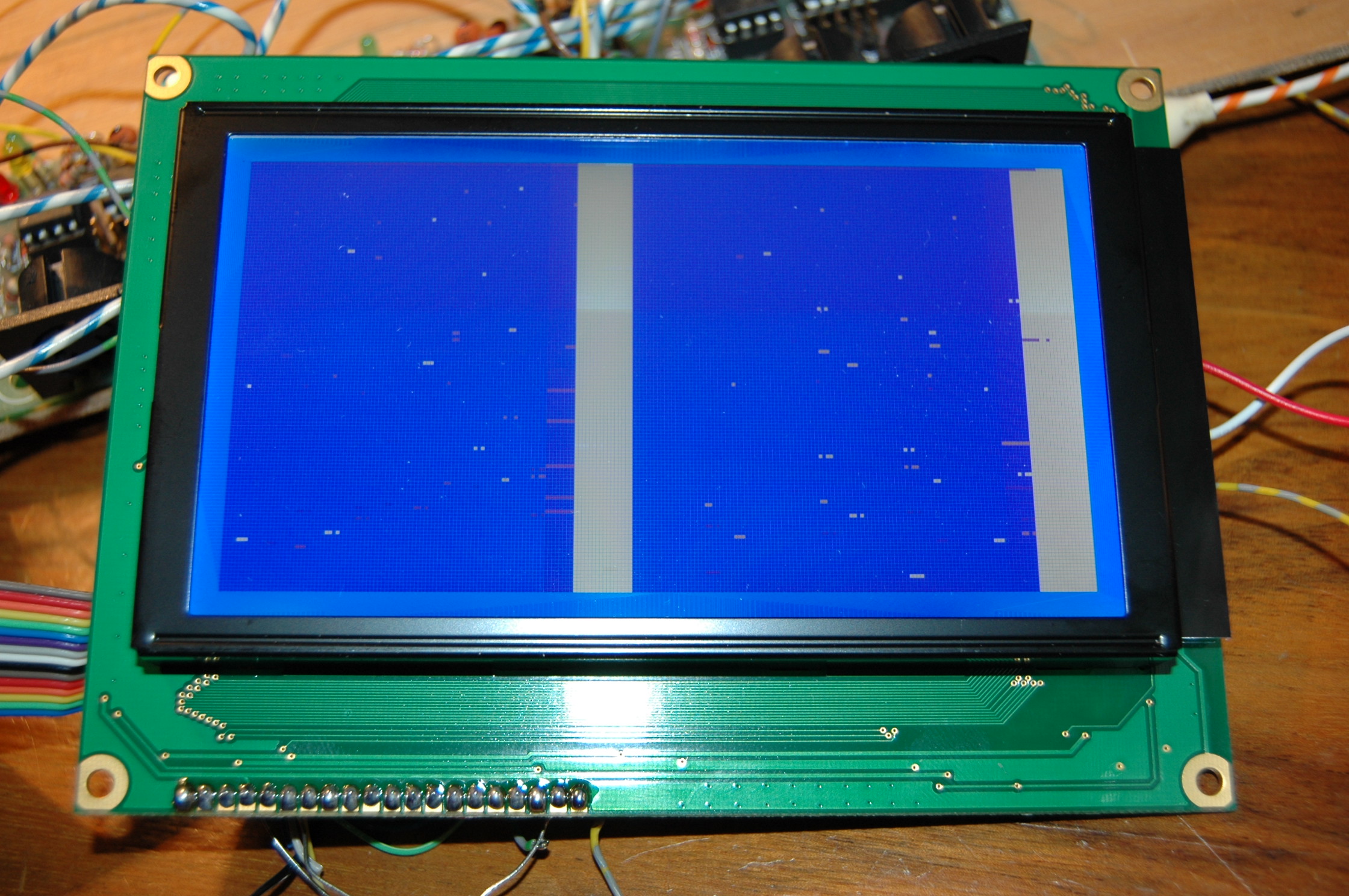
I own the W240-7KHLW, so it needs 135mA. I did as you said to use an external power suply the 7805 was really hot (but did not burn myself 8)). I connected the anode and cathode from the LCD to the power suply, this works fine. Also the hex uploading works perfectly now! Only still no text… I added some pictures of the connections and the screen I got. It’s like running things and two big bars.

I double checked every pin and I’m pretty sure it’s good now:

LCDpin 19 and 15 are pulled down

LCD pin 18 and 16 are pulled up

all the other pins are just like you said before.

cheers

Here’s another picture of the wiring,

I just checked the display without the external suply so there was no backlight and it seems that I don’t have this snow particles. It could be that I need the place some condensors to “filter” the 5V line. I only see those two big vertical bars as you could see on the other picture.

Hi.

I wouldn’t worry about the ‘snow’. This simply shows that the display has not been initialized properly. Usually when a GLCD first powers up, it’s RAM contains random values, the last section of USER_LCD_Init will clear all display RAM.

This does show that the display is either not talking to the PIC (wiring problem) or there is something wrong with the initialization sequence.

I have done a quick comparison between what the MIOS driver should be sending and the recommended initialization sequence from the lcd-module.com website and they look pretty close. There are some differences but I don’t know enough about the display to know if they are important!

I will see if I can find any more info about this display (in English) and I will let you know.

Phil

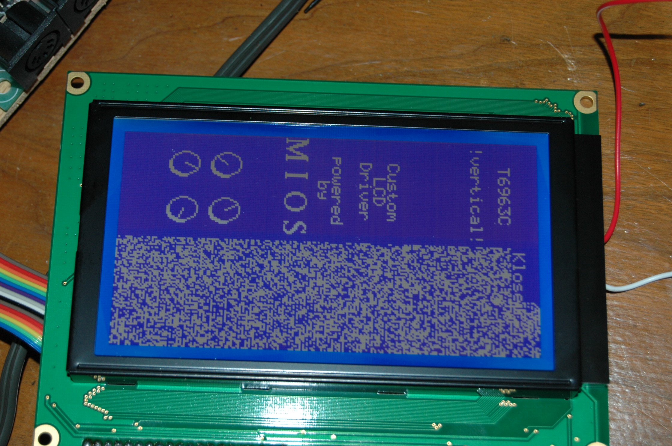
Remember, that first pic is sideways - the screen should be vertical :wink:

Indeed picture in the wrong direction  :stuck_out_tongue:

I send an e-mail tot the lcd-module.de contact and I got this answer:

  • wrong connection

  • cable longer than 10cm (it’s 15cm here)

  • broken cable (checked the wiring a zilion times)

  • wrong power supply

  • wrong interface timing

  • missing GND

  • bad levels on bus (also trise and tfall times)

For them this could be the reasons…

thanks

So, as we know the driver is good (it’s not timings, etc, as it works on all other 6369c), it’s all the stuff we already knew :stuck_out_tongue:

15cm long cable is kinda longish… All still comes down to connection problems… Yaknow it is possible you got a DOA though …

I think if it was me, at this point I would fire up my oscilloscope and verify that data is reaching the pins of the display. I guess that you don’t own a scope though?

If you are absolutely certain that it is wired correctly then we are really looking at either faulty PIC I/O pins or a faulty display. Either is possible especially if (like I often do) you wired things wrong initially… PIC’s are incredibly robust but it is possible to kill inidividual pins.

It may be worth investing in a cheap 16x2 CLCD display. These can be picked-up for a few euros and are easy to wire and are definately fullly supported by MIOS.

If you are going to build any more Midibox projects in the future, i’m sure you will use it. I keep the first 16x2 display that I bought for just this reason. If I think I may have blown something, I plug it in to check if the PIC is still working :slight_smile:

Cheers

Phil

Some good news at last!

It works  8) your last ideas put me to do some new testing, I changed the PIC that was on the board with the one from my MBLC work. I uploaded the T6963 vertical project and it just worked.

The old pic does work with CLCDs (tested it wit the srio_interconnections_test), but every time I upload the T6963 hex, I got this to bars on the GLCD about which we talked before.

The versions of the two pic’s are different:

The old one has Mios bootstrap v1_2 on it (2006)

The new one has mios V1.9F

Can it be that there’s a difference between the two loaders? because it’s so strange that the one with the older version does work with CLCDs but not with the GLCD (I think it’s not really broken…)

And yet another question:

Any hints on how to start editing the driver?

Another big thanks for all the help you provided!!

MidiBox rules :smiley:

Regards