Great, please sign up here:
Great, please sign up here:
Perhaps a question for TK: there is a small amount of “ghosting” e.g. when a sequence is running one LED is dimly lit 8 steps behind the current one. Was this ever seen before? It isn’t bright enough to make it through the silicone button but I should mention it and wonder if there’s a possible hardware (or software) fix before going for a new board rev.
In terms of current, running the entire 16x16 group illuminated blue (i.e. step active) draws about 560 mA. Thus it would be good to have a high current PSU feeding the SEQ; for example, I have a Meanwell 2.5A switching PSU for my 5V line. Unless your musical tastes are quite different to mine, it should usually be around half of this. I did add an extra header for power, and could add a second hole for a connector on the case if requested, if your existing SEQ PSUs aren’t juicy enough. Please let me know in advance if this is needed.
I think it would be a very good idea to add an extranal power option to the case, maybe two holes the same size as the hole on the MBSEQ back panel for a DC socket and switch. I would like to have the option to use an extranal PSU.
Looks like it shouldn’t be a problem to optionally add holes for power switches (I will confirm orders and collect addresses etc.).
To check: the switch and barrel connector holes are 13x12 mm and 11.1x9.1 mm as per TK’s Schaeffer file? I notice a lot of SEQs with a lot of different power entry requirements, I’d have to settle on one design.
How about you keep it really simple and add two holes approx 3mm in diameter spaced approx 30mm apart on the rear that can be used as pilot holes so the owner can drill their own holes for a power switch and connector if they want? This would work for me anyway.
latigid on, have you completed your build yet? I’m very interested!
How about you keep it really simple and add two holes approx 3mm in diameter spaced approx 30mm apart on the rear that can be used as pilot holes so the owner can drill their own holes for a power switch and connector if they want? This would work for me anyway.
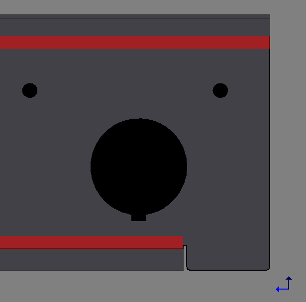
Is this okay for you? You would have at least 14 mm diameter clearance. Feel free to suggest another idea if you like, the red zones are essentially where the case bends. Remember that this is aluminium, not steel, so it is no trouble to drill if you wanted to wait until you have all the parts at hand. It’s a bit difficult to place the holes without seeing the parts you’re using.
latigid on, have you completed your build yet? I’m very interested!
Everything is more or less working, but I should test a new PCB to be sure. If you like there’s a waitlist for the next batch in the Bulk Order section.
Can I request that the polit holes have their centre in line with the centre of the larger hole (which I guess is for the DIN connector) on the vertical plane?
Can I request that the polit holes have their centre in line with the centre of the larger hole (which I guess is for the DIN connector) on the vertical plane?
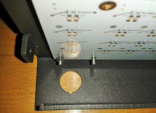
This shows the internals, I don’t think it’s possible to fit both in a vertical line.
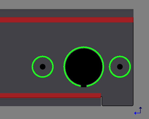
Horizontal I can do, the green outlines are 10 mm. But of course it’s nicer to have all the cables out of the way on one side.
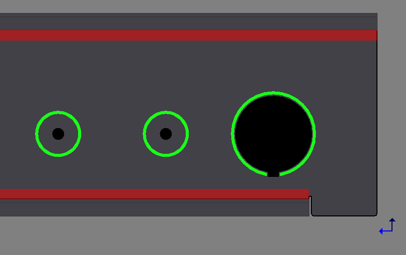
Ok, could both the holes be on the left side of the DIN cutout?
Having one to the right looks like fitting a switch/socket could be a little bit tight in some cases. If the fitted hardware was to require a 10mm hole for example, the bezel would probably require an extra few mm.
Bonus: you could use the holes as sockets for CV inputs to control the SEQ. ![]()
Would need to implement a diode protection circuit, but there are two a “muck” areas onboard.
Looking good!
Lamouette asked if the illumination is okay in sunlight. I shone a 10 W fluoro lamp on and you can still make out the colours although it’s much better when it’s a bit darker. In any case I’m happy with the brightness.
Darn, that does indeed look good. Very very cool!
Cool!
How many colors am I supposed to see? I see four (green, blue, and two mixtures) - is this correct?
Thanks!
Maybe it’s weird lighting, but this BLM has three colours: blue, green and cyan (and off). The way I’ve wired the LEDs would correspond to TK’s green, red and yellow. You could also choose to swap the green with red, then you get pink as the third colour.
It looks awesome! And sorry for not jumping on the list. I’d really like one, but still have no studio space! ![]()
The colors appear different probably due to cam shutter effects in conjunction with pulsed/matrix driven LEDs. The middle section (darker) may have been in a different duty cycle than the others ![]() I have the same problem when filming the Programma and a few synths ;-). If taking still photos, it helps to use a long exposure time (a second or two) and to use a small aperture/low iso setting.
I have the same problem when filming the Programma and a few synths ;-). If taking still photos, it helps to use a long exposure time (a second or two) and to use a small aperture/low iso setting.
Many greets!
Peter
beautyfull!
Interesting, it looks like Mouser will soon stock the button pads. If so, that’s a great way to get almost everything in one order. I’m a bit busy but I’ll try to get PMs out in the next few days to confirm addresses, payment details etc.
Mouser part:
485-1611
Currently out of stock but I’ve requested a delivery quote.