Quote from: Gridracer on Yesterday at 02:58
…
2.:
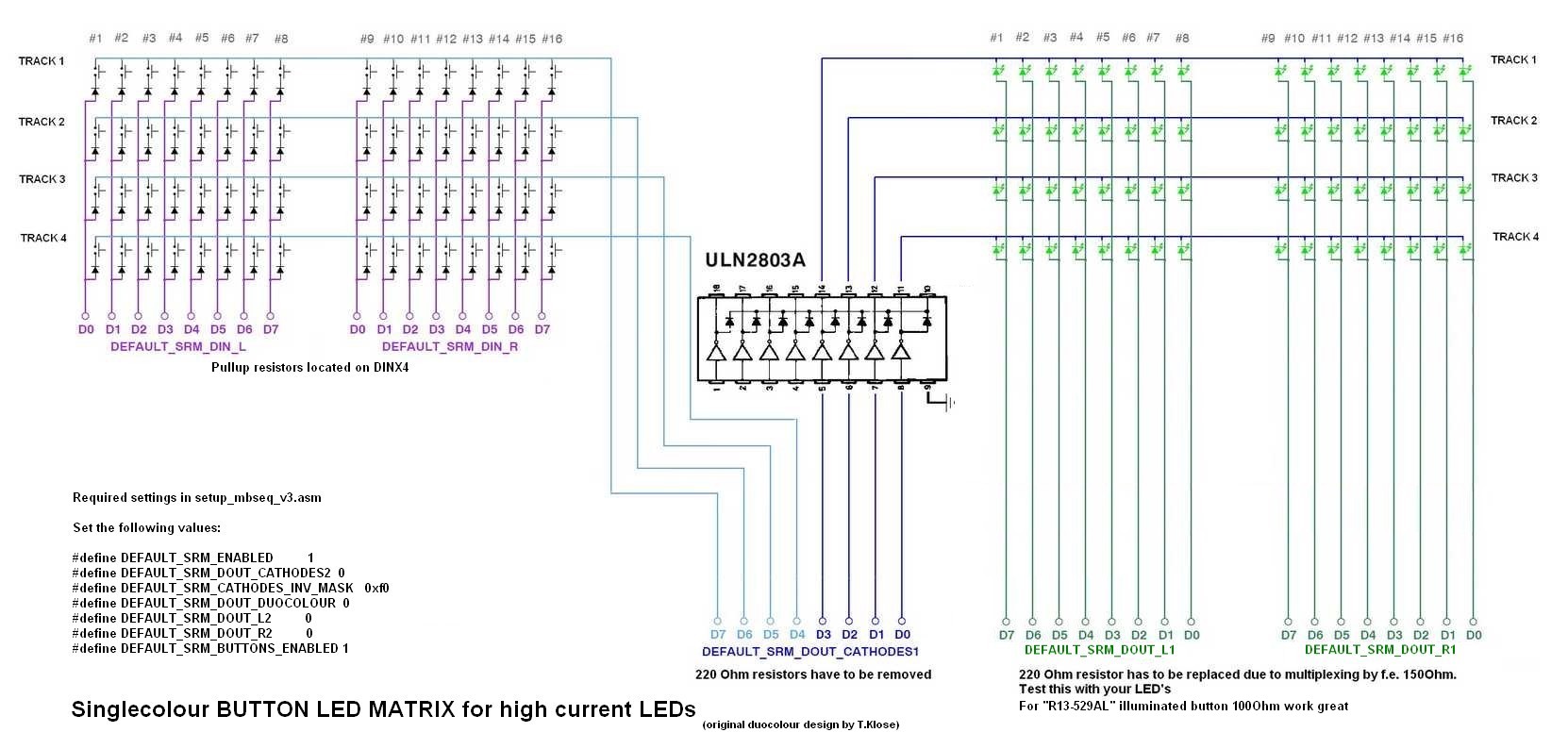
As I use use sink drivers I will not use register “DEFAULT_SRM_DOUT_CATHODES2” and define it as Number 0,
All buttons and all LED cathodes are connected to “DEFAULT_SRM_DOUT_CATHODES1”
??? But I think I found in setup_mbseq_v3.asm that the shiftregister DEFAULT_SRM_DOUT_CATHODES 2 is only required due to the high power of 16LEDs which is so reduced to the power of 8LEDs.
So with sink drivers it is also not required. It is commented that it should be set to 0 just as I plan and so can use the one set free on the DOUT4x module for something else.
; define the shift register to which the cathodes of these LEDs are connected
; Note that the whole shift register (8 pins) will be allocated! The 4 select lines are duplicated (4 for LED matrix, 4 for button matrix)
; The second DOUT_CATHODES2 selection is optional if LEDs with high power consumption are used - set this to 0 if not used
#define DEFAULT_SRM_DOUT_CATHODES1	5
#define DEFAULT_SRM_DOUT_CATHODES2	8
Or did you mean changing line #define DEFAULT_SRM_DOUT_CATHODES2 from8 to 0 in setup_mbseq_v3.asm and adding the sink drivers to the DOUT module with circuit/code changes??
Quote … 4.: Point 1-3 made me save some registers, to save a DOUTX4 module i only have to change the register number in setup_mbseq_v3.asm and nowhere else, (besides recompileing) …
As far as I understand the Inversion mask is required only to compensate the signal inversion that does the sink driver itsself, (as twice inverted equals out) so after the sinkdriver the button rows and LED rows are even again. I think it has nothing to do with the correspondance to the Tracks. But I am no expert. from looking at the circuitplan: http://www.ucapps.de/mbhp/button_duoled_matrix.pdf and regarding the notes to the inversion mask in setup_mbseq_v3.asm:
;          0xf0 - sink drivers connected to D0..D3
;          0x0f - sink drivers connected to D7..D4
I can only assume :-[ the following:
There are fourpossible connections:
A (to be prefered as it matches the circuit plan)
TRACK1: LED ROW connected to PIN D3 , BUTTON ROW connected to PIN D7
TRACK2: LED ROW connected to PIN D2 , BUTTON ROW connected to PIN D6
TRACK3: LED ROW connected to PIN D1 , BUTTON ROW connected to PIN D5
TRACK4: LED ROW connected to PIN D0 , BUTTON ROW connected to PIN D4
#define DEFAULT_SRM_CATHODES_INV_MASK 0x f0
B (If you have “mirrored” the connection compared to the circuitplan:Buttons on the right pins, LEDs on the left pins)
TRACK1: LED ROW connected to PIN D7 , BUTTON ROW connected to PIN D3
TRACK2: LED ROW connected to PIN D6 , BUTTON ROW connected to PIN D2
TRACK3: LED ROW connected to PIN D5 , BUTTON ROW connected to PIN D1
TRACK4: LED ROW connected to PIN D4 , BUTTON ROW connected to PIN D0
#define DEFAULT_SRM_CATHODES_INV_MASK 0x 0f
No the in my eyes unlikely ones:
(highest TRACK number corresponds to the highest Pin Number)
C
TRACK1: LED ROW connected to PIN D0 , BUTTON ROW connected to PIN D4
TRACK2: LED ROW connected to PIN D1 , BUTTON ROW connected to PIN D5
TRACK3: LED ROW connected to PIN D2 , BUTTON ROW connected to PIN D6
TRACK4: LED ROW connected to PIN D3 , BUTTON ROW connected to PIN D7
#define DEFAULT_SRM_CATHODES_INV_MASK 0x f0
B (If you have “mirrored” the connection compared to the circuitplan:Buttons on the right pins, LEDs on the left pins)
TRACK1: LED ROW connected to PIN D4 , BUTTON ROW connected to PIN D0
TRACK2: LED ROW connected to PIN D5 , BUTTON ROW connected to PIN D1
TRACK3: LED ROW connected to PIN D6 , BUTTON ROW connected to PIN D2
TRACK4: LED ROW connected to PIN D7 , BUTTON ROW connected to PIN D3
#define DEFAULT_SRM_CATHODES_INV_MASK 0x 0f
Am I on the right way?? or do i just have no clue of what I am trying to do ???
I will start with version A but it would be nice to leave this not an open question.