dipCoreF4 and dipBoardF4, a compact Core.


Hello,

This is about a new STM32F4 mbhp, a very compact one.

This concept is an answer to these three topics:

http://discourse.midibox.org/t/topic/20177

I tried to draw the most compact core and mbhp board.
It’s an STM32F405RG instead of the regular 407VG. The 405RG is the smallest package of the M4 Series, this is a LQFP64, a 10x10mm package with only 64 pins.
Because these two Processor are from the same family, we don’t need deep changes in MIOS32. They have exactly the same functions, memory, speed and peripherals.

I put the STM32F4 on a DIP-40 format pcb, in order to get a core that can also replace a PIC in some application, I strongly think of my sammichSid. At the same time it must provide the legacy functions and ports of MIOS32 of course.

Some compromise have been made in comparison to a 407VG mbhp.

  • Only 2 MIDI I/O.
  • J15, the LCD port is now a serial one only(SSD13xx).
  • No more general purpose port J10x.

This is the list of the ‘remaining’ ports and changes.

  • J1A and J1B are the USB and Power ports, J1A is compatible with latigid on’s USBwCore module. J1B can be a common header on top or a Micro-Match connector on bottom to stack another board under.
  • J4 is a dual I2C connector, I put both on the same connector to save space.
  • J5 is a 2 channels only ADC, they can be used for expression pedal input for example.
  • J8/9 and J19 stay the Legacy 5V SPI ports, the dipCoreF4 includes the octal buffer(74HCT541);
  • J11 is now a 6pin and 2 MIDI I/O port.
  • J16E is the 3.3V SPI port, commonly dedicated to the SD Card it is compatible with latigid on’s RES-SD modules. it is extended by the Reset input, the user button and 2 outputs for LEDs.
  • J18 has changed, it is now able to connect a CAN tranceiver, but stay compatible with the MBNET connection.

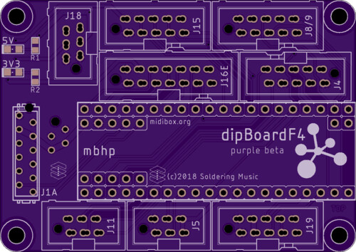
About the dimension, the ensemble is very compact 65x46mm, but the Core can be used alone and measures 51x17.8mm.


A 3D view of the ensemble(sorry this is not a render, I shoot the screen):


You will find some more information on the dokuwiki, dipCoreF4 and dipBoardF4

Feel free to ask me question or give me any constructive criticism.

I will order some board very soon, if some want to participate in the tests they are welcome, just contact me. I will provide the beta boards for free I just ask you to play the game and seriously help me to improve it :wink:

Thank you
Best regards
Bruno

PS: sorry for my English as usual :wink:


Hi,

2 beta testers! One last?! :slight_smile:
 

and
This is the eagle lib for the dipCoreF4, it will be easier to integrate in your design.

Here:  dipCoref4_beta.zip!

Fell free to create the equivalent for Kicad…

Best regards
Bruno

1 Like

yes that helps alot! thx

I put tented via on both board for easier soldering and better silkscreen…

This is really nice.  It’s looking good so far.

Someone else is interested to test this Core?
I’m in holidays and I want to order the boards quickly.

Best
Bruno

Oh, in for sure.  I have clamshells for F405s to flash the bootloaders too

2 hours ago, Altitude said:

Oh, in for sure.  I have clamshells for F405s to flash the bootloaders too

NB: A Discovery can flash it onboard. SWDIO and SWCLK are on the DIP40 pin 13 and14 (old xtal IO).

2*dipCoreF4 + 1*dipBoardF4 is fine for you?

Bruno

works for me :slight_smile:

I converted your Eagle Library to Kicad Library (with  eagle-lbr2kicad-1.0.ulp)


not tested on any PCB-Fabrication yet… so be careful (i use kicad 5)

dipCoreF4_beta_kicad.zip


also addet a 3rd Symbol for the 48pin - a smaller one:


Just now, Phatline said:

I converted your Eagle Library to Kicad Library (with  eagle-lbr2kicad-1.0.ulp)

dipCoreF4_beta_kicad.zip

not tested on any PCB-Fabrication yet… so be careful (i use kicad 5)

Seems fine, great!
Think to set 3V3 Power supply pins as Output type! To avoid any mistake. VBUS(5V) is an Input type of course.

Just now, Antichambre said:

Seems fine, great!
Think to set 3V3 Power supply pins as Output type! To avoid any mistake. VBUS(5V) is an Input type of course.

ok, done i replaced the file above.

They where set as

3,3V and GND was Current-INPUT   -  I changed them to Current-OUTPUT,

and

VBUS   was BIDIRICTIONAL - now they are set as    Current-INPUT

25 minutes ago, Antichambre said:

Seems fine, great!
 

Maybe i am wrong - but i miss PB2 for SD-Card (maybe i am blind, i dont see it)

at least you told me how to connect it right on the DiscoBoard see this:

< base_url >/topic/20864-sd-card-slot-socket-supplier-footprint-and-interconnection/?do=embed&embedComment=181555&embedDo=findComment

but maybe you changed the PinOut on MIOS-Side - and this is one of the changes ( if then - please say wher to connect “CD/DAT3” to DipCore


thx mike

do i understand right:

the DIP-CORE is made to be Powered Up by micro USB only     - so: i dont need to integrate a Power-Jumper anywhere in my Design?

48 minutes ago, Phatline said:

but maybe you changed the PinOut on MIOS-Side - and this is one of the changes ( if then - please say wher to connect “CD/DAT3” to DipCore

Right! Refer to this chart for changes:

For easier routing PB2 was replaced by PA4, in MIOS32 side also.
 

42 minutes ago, Phatline said:

the DIP-CORE is made to be Powered Up by micro USB only     - so: i dont need to integrate a Power-Jumper anywhere in my Design?

Not USB only, you can use external 5V connected to VBUS on Pin44 or on J1A or J1B of dipBoardF4.

I’m currently preparing an USB board where VBUS from type B connector(device mode) is switched off when VIN(external power) is present…

Best
Bruno

PB2 > PA4  = SD-Card Dat3   >>>   OK thx for INFO.


as i am currently redesign my CC-Looper-Circuit/PCB… i have (maybe) a last question:

? where to take +5V on the DipCore32 -  to powering for example 165/595 registers?    -   you sayd VBUS is input, so i assume i dont get it from there?

thx 4 info

A Note:

In Kicad you cant connect: on one Component, multiple Power-Outputs, to a single 3,3V plane…

you have to make then two seperate planes for your connected Components like “+3,3a” and “+3,3b”

or

change in the Component one of the 3,3V Outputs to bi-directional (for example - so there is no confligt in designrule-check)

or

you dont connect anything on the second Power-Output (but that would eliminate the Routing Benifit of a “Air wire” over the dipcore…)

Just now, Phatline said:

? where to take +5V on the DipCore32 -  to powering for example 165/595 registers?    -   you sayd VBUS is input, so i assume i dont get it from there?

From the same external source where you connect VBUS of the dipCoreF4, Simply see it like a component, you’ve got to supply it in 5V and it will provide you the 3.3V. The Core is the 3.3V regulation too(this is not different to the others cores).
Remember, there’s a 74HCT541 onboard, all J8/9 and J19 output pins are in 5V. Usually this level shifter is on the mbhp, but here the Core is dedicated to MIOS32 then I put the 541 directly on it.
 

Just now, Phatline said:

In Kicad you cant connect: on one Component, multiple Power-Outputs, to a single 3,3V plane…

You can’t internally connect to physical pins to the same signal? Strange, but I can’t help on this, I don’t know Kicad.

Just now, Antichambre said:

From the same external source where you connect VBUS of the dipCoreF4, Simply see it like a component, you’ve got to supply it in 5V and it will provide you the 3.3V.
Remember, there’s a 74HCT541 onboard, all J8/9 and J19 output pins are in 5V. Usually this level shifter is on the mbhp, but here the Core is dedicated to MIOS32 then I put the 541 directly on it.

i know that the HCT541 is onboard, i already connected the 165 and 595 datalines…that was no problem.


i dont know what you mean-it is not clear for me: with the VBUS and external source… > i want to plugin a USB-Cable, and power my Core and the J8/9 with it

* i dont use a Dip-Expansion-Mother-Board - i plug the DipCore into a UI-PCB where all shiftregisters and all other components are already on it.

* a simple example Circuit: a 595 and 6n136 are connected to the DIP-Core, where do they get 5V? (from the VBUS-Pin? is this the source?)


thx 4 help

In the dipCoreF4 the internal plane 1 is divided like this:

Between VBUS and internal +5V there’s a PTC fuse F1 which protect VBUS from over-current.

You can use VBUS(Pin44) as output and supply your App PCB from dipCore USB. But F1 will not protect VBUS from your APP board 5V load.
I didn’t think it like that, in your case, you will design a dedicated box for your CC looper UI-PCB then you will put an USB connector or an external power somewhere on that box. And in this case you’re not obliged to use and solder the dipCoreF4 USB. The dipCoreF4 is like a component and your UI-PCB provides the 5V to it.

Between Your App USB connector and pins 46/43 some rules are usually followed to preserve differential pair DM/DP.

  • USB signal pair traces should be trace-length matched. USB 2.0 Full speed (12Mbps) can survive a 1mm difference.

  • Avoid 90° angle in trace. I used to round it a little bit.
     

Hope this helps you…