the configurAtion is 2 chips 74hc165n I only need 8 buttons on my midi box 64
the problem is when I press 1 button nothing happens but… If I press 2 at the same time yes… I mean it send the midi command, for example if I send to ground pin 3 of the 74hc165n nothing hapends but if I send to ground pin 3 and 4 at the same time it send the midi command… Same with 4 and 5 and so on, it’s so strange, I have built 5 midi boxes and never hapends something like this, I have tried 3 different PICS with the same results, what can be the problem?
Wild guess, if you are using resistor networks on your DIN module, can you check that these are of the required “bussed” type?
The resistor network needs one common pin connected to ground 5V, this pin is connected to every other pin via individual 10k resistances - you can measure that with a multimeter…
The described behaviour sounds like you maybe have got the wrong type of resistor network, where the 10k resistances are actually between the pins (but not going to common ground 5V).
Just to correct you there hawk, the resistors are pull ups to +5V. The other point to check is if resistor networks are oriented with the dot aligned with the PCB silkscreen. If this is a DIN kit from SmashTV then you have the correct components. Something else to consider is that DIN (or DOUT) modules will not cascade unless all chips are installed because the specific SI or SO data signal is routed through each subsequent shift register.
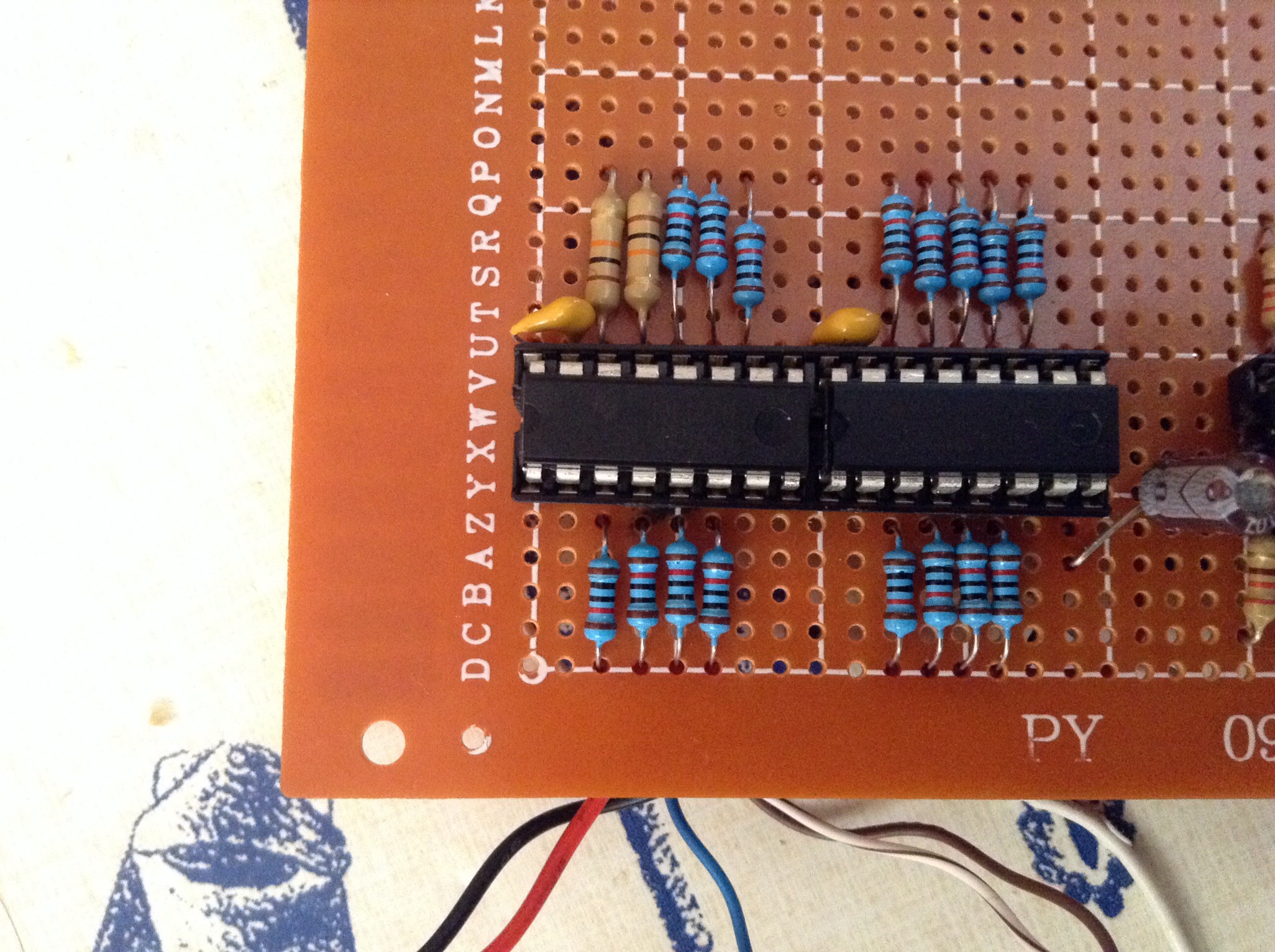
theres no resistor network, and it’s made on proto board , I have check every pin to 5v and I have perfect 10k , I know it’s crazy, it is possible the software has something to be here?
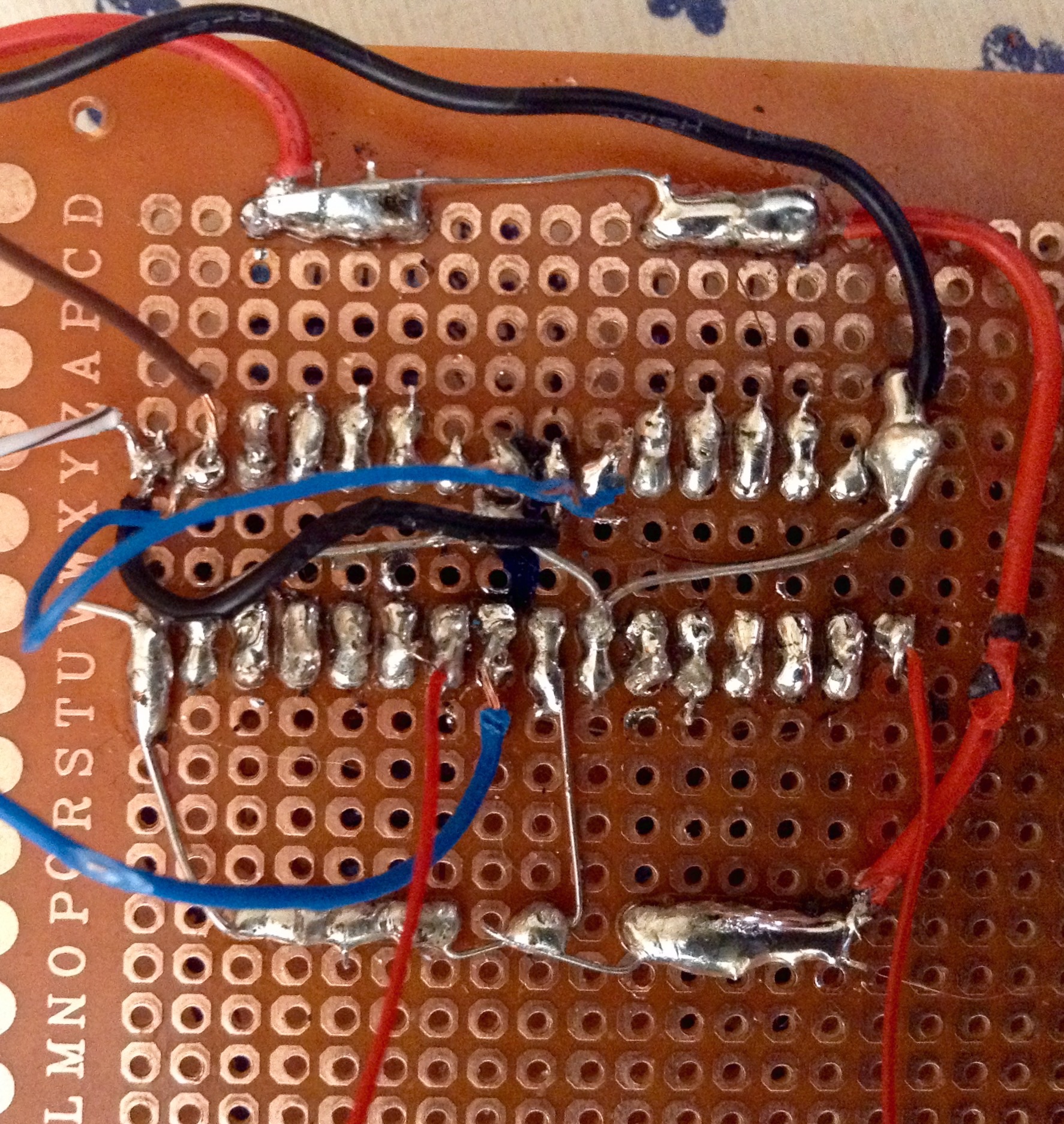
in this case, and as we love puzzles and mysteries on here :-) - could you post a high-res photo of the front and backside of the proto board?
The best test would be to use the same core and software and just swap the DIN board against a known-working one… If this also does not work, it is a software problem, if it does work, it is a hardware problem…
I don’t know much about MB64, but if the number of shift registers configured in software is greater than what you have installed I can imagine their addressing could get messed up. Feel free to post a pic, that always helps.
; This DIN map allows you to customize the MBMF application to different hardwares
; The MBMF dump structure allows the use of up to 64 buttons, they are grouped to 8 buttons per shift register
; Define the used shift registers for the buttons here
; the shift registers are counted from one - means: 1 for the first, 2 for the second, etc…
; mark unused button groups with 0 #define DEFAULT_DIN_SR_PIN_01_08 2 #define DEFAULT_DIN_SR_PIN_09_16 3 #define DEFAULT_DIN_SR_PIN_17_24 1 #define DEFAULT_DIN_SR_PIN_25_32 4 #define DEFAULT_DIN_SR_PIN_33_40 5 #define DEFAULT_DIN_SR_PIN_41_48 6 #define DEFAULT_DIN_SR_PIN_49_56 7 #define DEFAULT_DIN_SR_PIN_57_64 8
Hm, it is a bit hard to tell, there are a couple of spots, that look a bit sketchy, no offense intended!
E.g.. I think there is a connection of the DIN wire that is routed to the switch (in the last picture, the first red wire leaving the screen vertically) to its neighboring pin.
Then: are the big resistors also 10k resistors? Can’t see their colors too well…
Then: in the last picture, the right IC, upper right connections, where the big solder blob with the black wire nearly meets its neighboring pin…
In retrospective, I’d suggest to:
a) follow latigid ons recommendation and check, that the software is configured correctly and especially unneeded input shift registers are disabled
b) test with another DIN module or rebuild that section once again…
as I supposed the problem ends when I mount the 4 chips, now all works perfect ( or looks like), I think it’s a software problem( or configuration) , if someone knows how to solve this for my future boxes I will appreciate.
Btw, how can I use the first 4 buttons as midi triggers?, I don’t use LCDs on my boxes and the first 4 buttons are use to control the box in the software, I’m talking about midi box 64
No, I don’t compile a new .asm just the original one , looks like the software it’s written to control 32 or 64 digital inputs and when an IC it’s no present the behavior its crazy
No, I don’t compile a new .asm just the original one , looks like the software it’s written to control 32 or 64 digital inputs and when an IC it’s no present the behavior its crazy
Exactly, you should instead disable the unused DINs and build a new .hex file otherwise the PIC is looking for registers which aren’t there!
OK guys, DOUT , works fine, I mean you can use the ICs you need, just you need to configure the correct outputs pairs with the virtual midi box software and that’s it . I only install 2 ICs on the DOUT board