After nearly one year of usage, the overlord cat concludes:
Will soon post a few more optional mods to increase daily usage pleasure even more…
After nearly one year of usage, the overlord cat concludes:
Will soon post a few more optional mods to increase daily usage pleasure even more…
Step 18: Stabilize Rotary Encoders (optional)
Parts used:
* JB-Weld
Description:
* If you have removed the detention of the encoders, you may have noticed, that it is quite difficult to close them properly again so that there is no unwanted wobble/movement when applying off-axial force to them.
* Even with calipers and some muscle, the encoders would not reach the stability of an unopened (still detented) encoder. Even worse, over time the clamps loosen a little bit, making things worse.
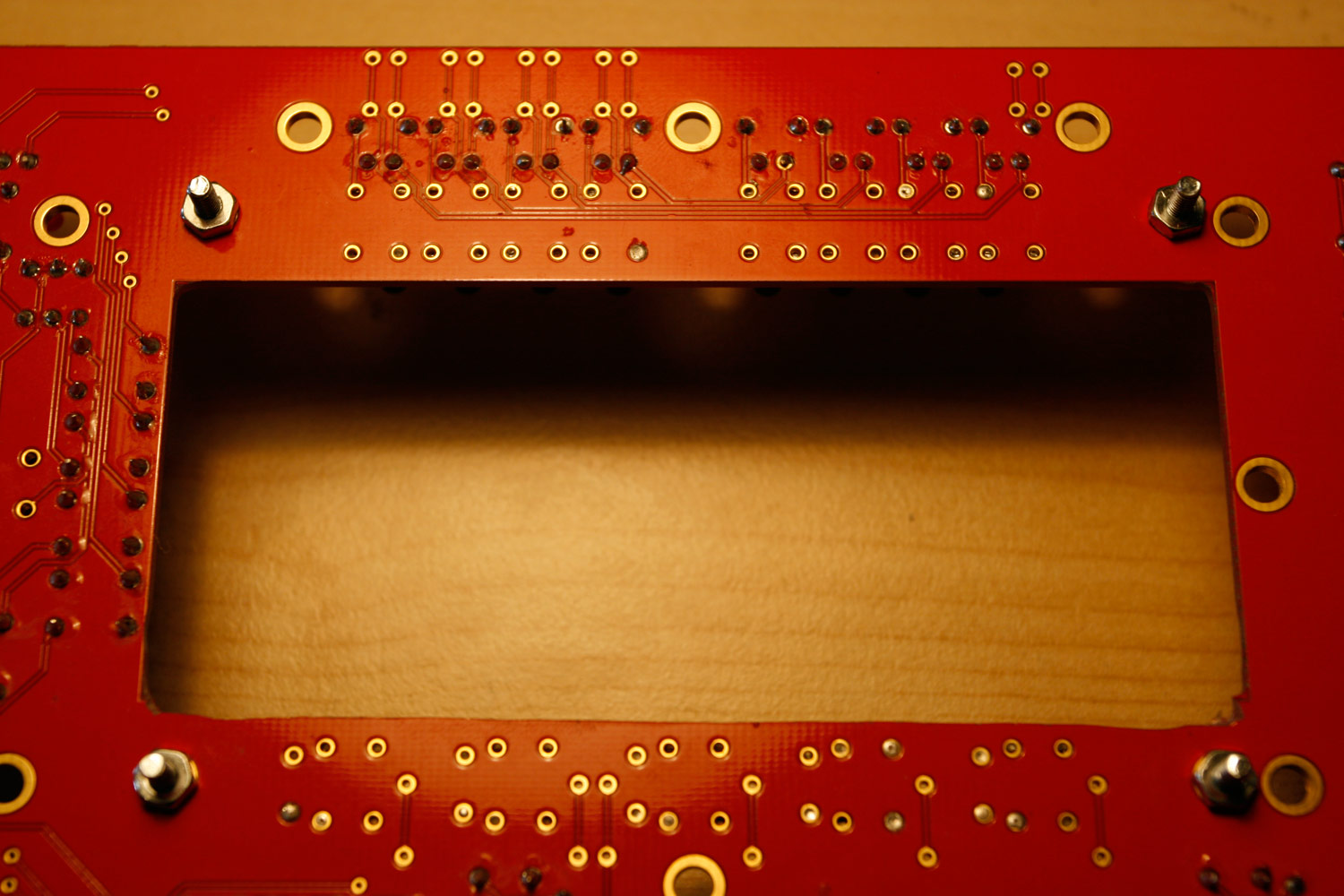
* Therefore I recommend to just apply four tiny blobs of JB-Weld on where the brackets meet the upper encoder case. It stabilized things a lot for me (photo 1).
* Make sure you don´t get any JB-Weld on the encoder screw threads, we will need those later on ![]()
Note:
Should you ever need to replace an encoder, use a wire cutter to cut it just above the PCB and then use a vaccuum pump from the backside and your soldering iron from the front side to suck out the short pin remainders.
Step 19: Create Knob Backlights (optional)
Parts used:
* 45 pcs SMD LEDs (1.5x3.0mm) (Red Water Clear Kingbright Standard SMD LED) (Mouser 604-APL3015SRCPRVF01)
* a roll of enamelled copper wire (.35mm diameter) (e.g. Reichelt CUL 35)
* a roll of standard electric insulating tape
* your favourite soldering equipment
* a soldering “helping hand” tool
* SMD calipers
Warnings:
This is a time-intensive task. It is only required if you have non-opaque knobs (like the transparent waldorf knobs), that can be illuminated via backlights. Also, I highly recommend to not enjoy excess caffinated beverages, because, ehm… the LEDs are small :-). As I started, I needed over 20 minutes per “LED Loop”, in the end around 10 minutes… and there are 15 of them…
Otherwise, it is very meditative and great training for smd soldering, so… lets begin :-).
First of all, I consulted a few people more firm in electronics than myself, and also read up on some tech resources… On each rotary encoder three LEDs should be mounted and wired in series for easier cabling… Normally, resistors in series to a LED are employed to limit the current that flows, because LEDs are not “linear” in current consumption… a very slight voltage increase leads to a dramatic increase in current… potentially over the limit and “burning” the LED.
In this case, every LED only gets 1/3 of 5V, which leads to very moderate current consumption which I measured with a multimeter. Assuming the 5Vs are stable, nothing bad happens to these LEDs.
This may vary when you employ different LEDs. Even if you use the same, always measure the current that flows, and verify that it is below the datasheet maximum. In many cases, 5V may not be enough to light three LEDs in series. You can then take +9V from the baseboard, but must then employ a resistor that matches your LEDs. In normal cases, please use a resistor and measure the current. I cannot take responsibility for burnt “direct-driven” LEDs. In fact, nILS takes all responsibilities :-).
Description:
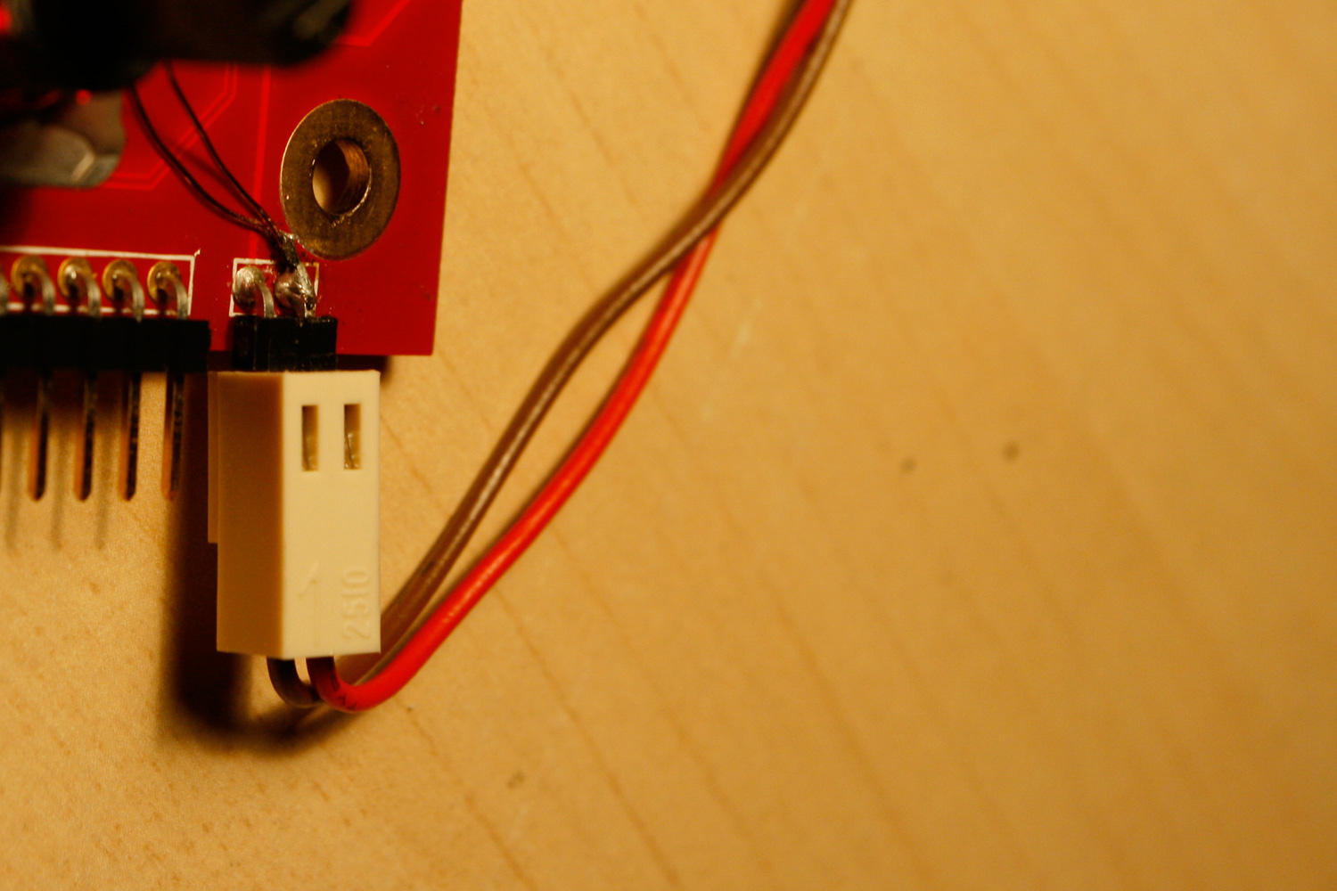
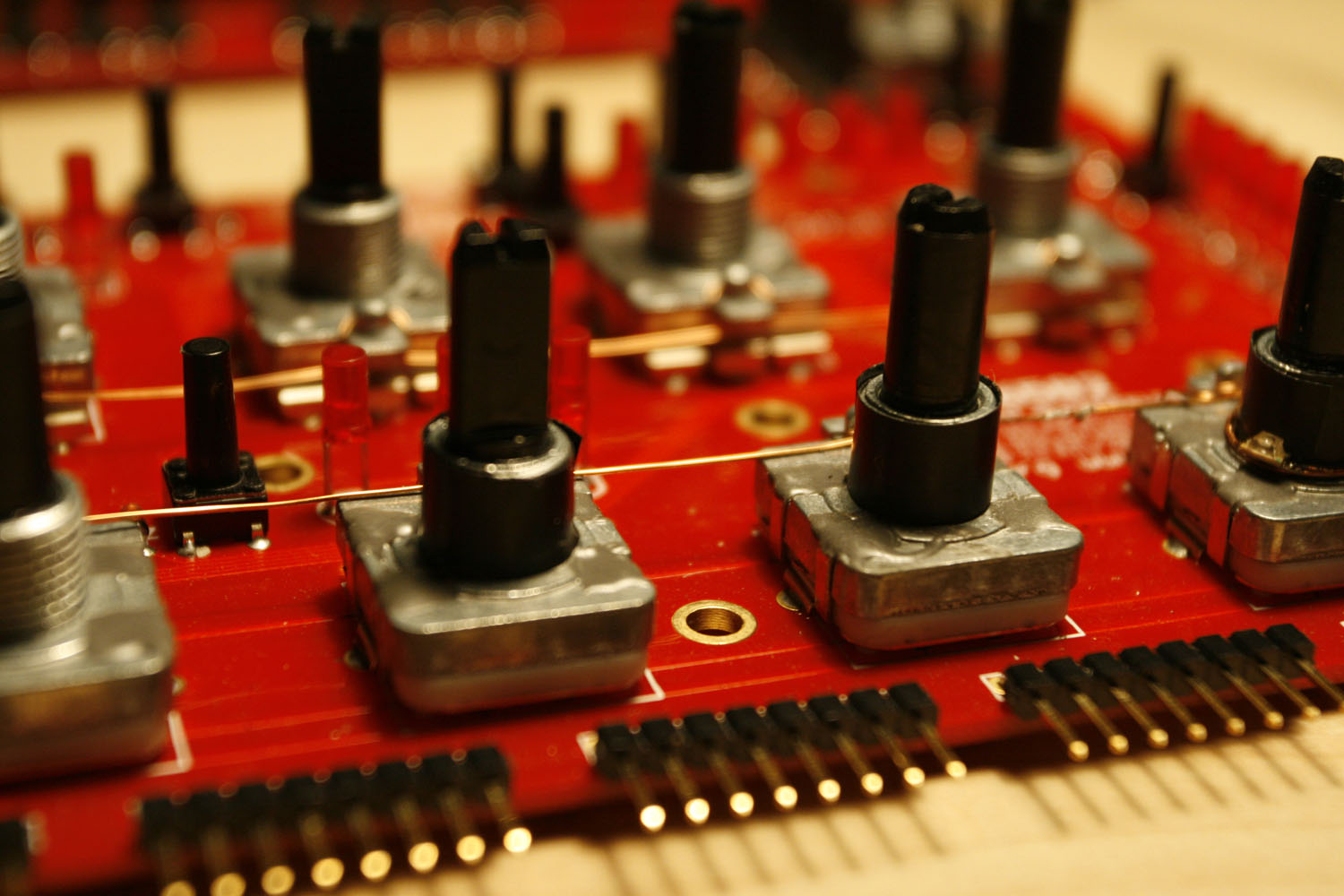
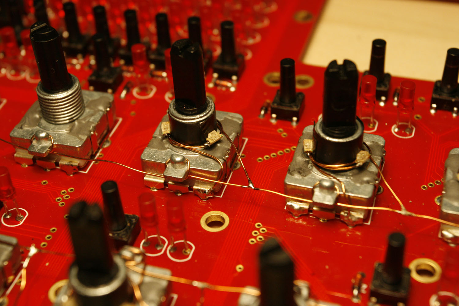
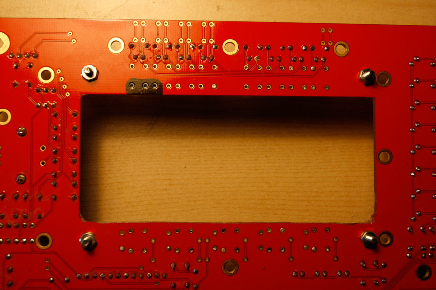
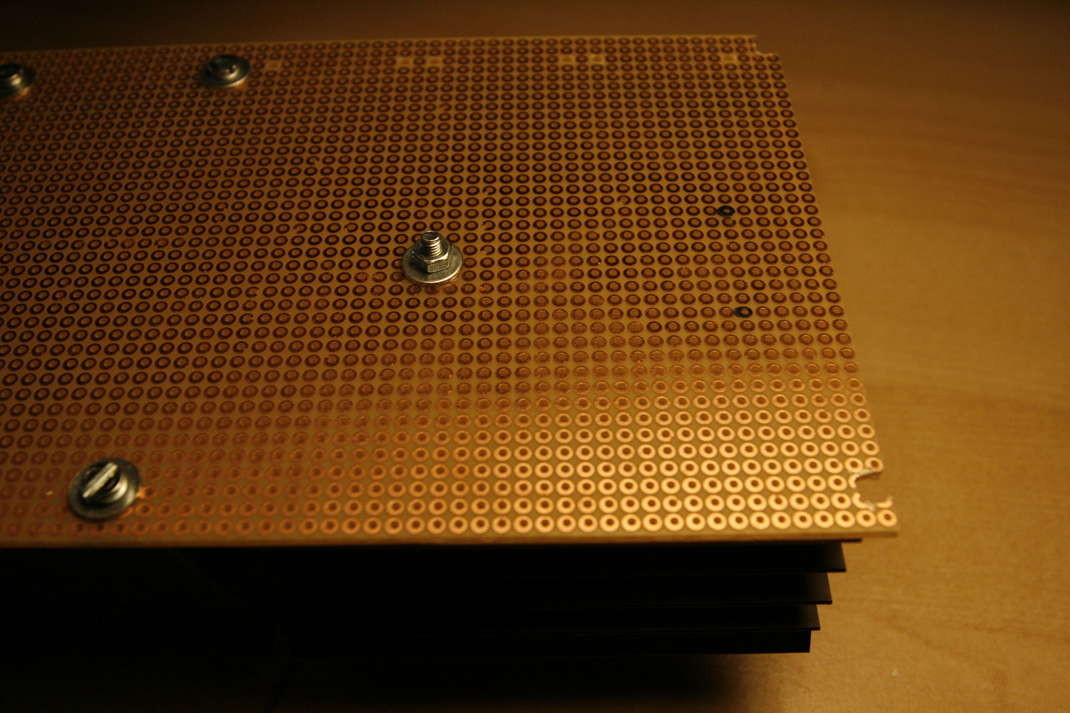
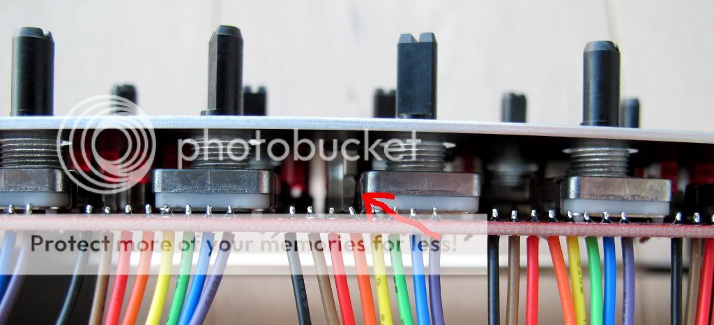
* Use the enamelled copper wire, connect it to the +5V at the CS corner connector and wrap it around all encoder housings, like a telegraph line :-). Be aware that your wire stays clear of any holes in the CS - the standoffs must be free and not “collide” with your copper wire (photos 1 + 2).
* Use one layer of insulating tape to cover the encoder shafts - you need to split it in half to have the correct height (photo 2).
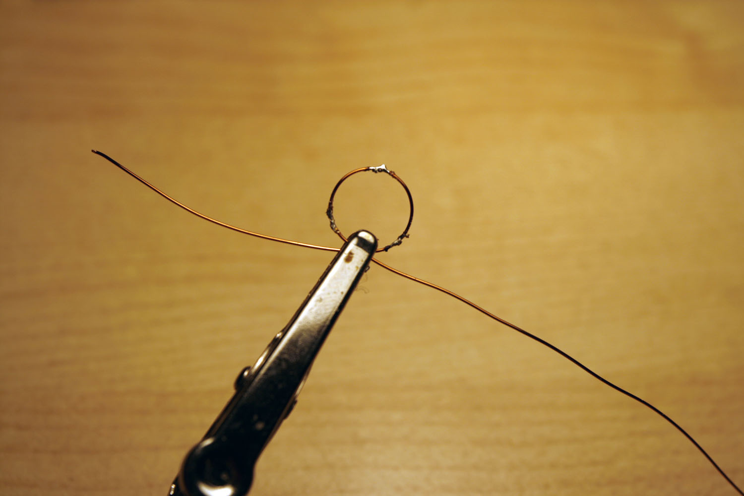
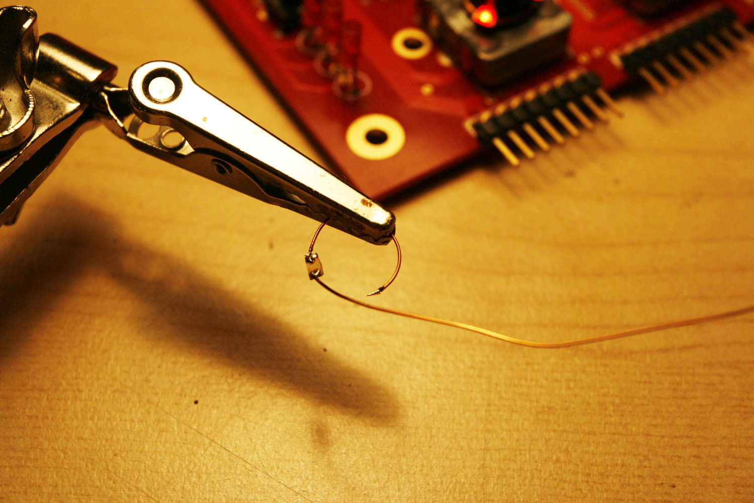
* Prepare a copper wire loop, by just wrapping a length of enamelled copper wire around an encoder shaft. Tin the loop at 120 degree intervals (photo 3). (You may need to have your soldering iron at a temperature higher than 400°C to melt the lacquer).
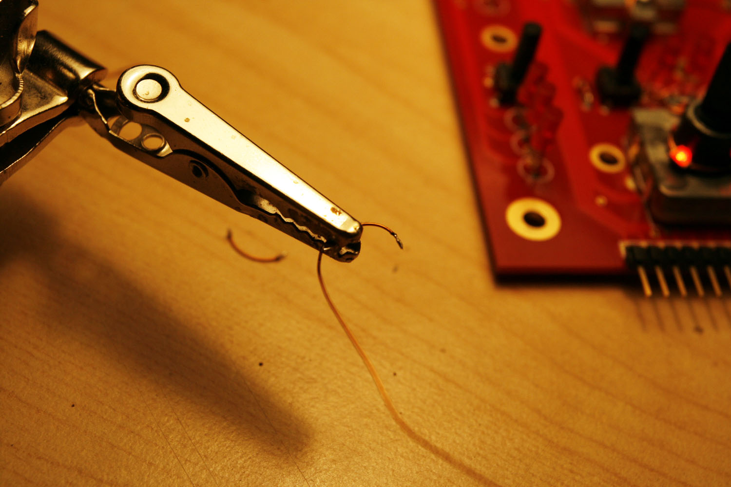
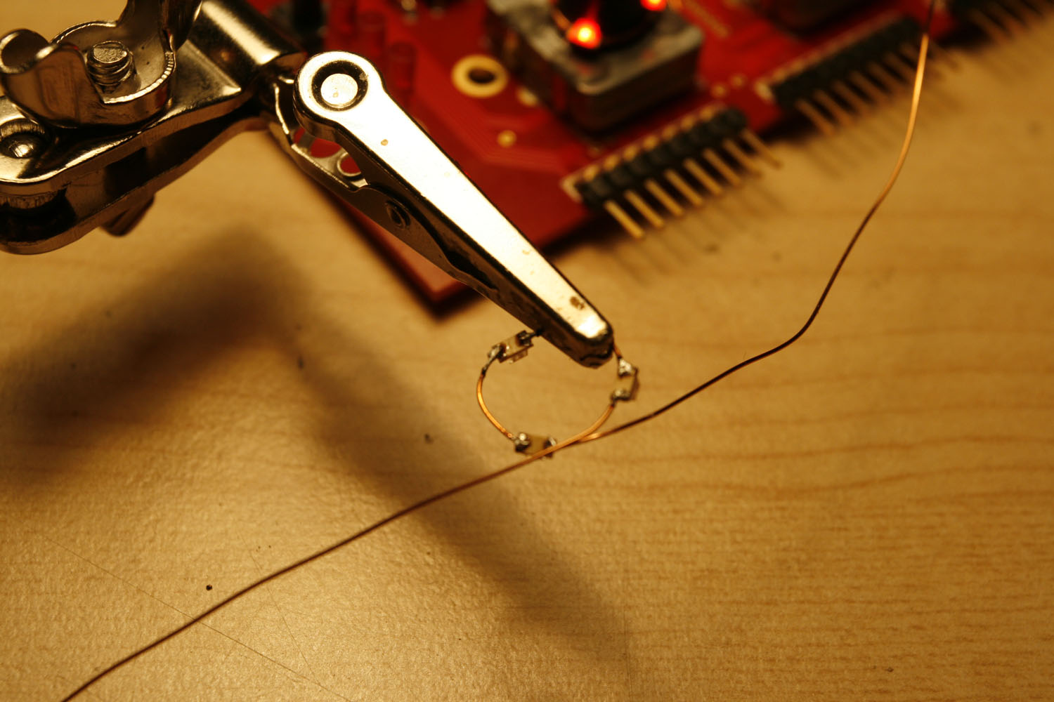
* Cut the wire at your solder points - if nothing went wrong, e.g. one of these frequent reality bugs occured, you should have four shorter wires ![]() - use a “helping hand” to solder the SMD LEDs and the wire pieces one by one, see photos 4-6.
- use a “helping hand” to solder the SMD LEDs and the wire pieces one by one, see photos 4-6.
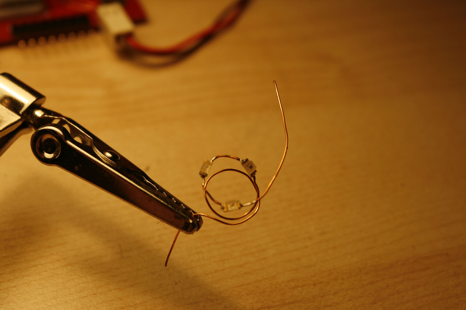
* Create a “standoff loop” that guarantees clearance from the encoder base (photo 7)
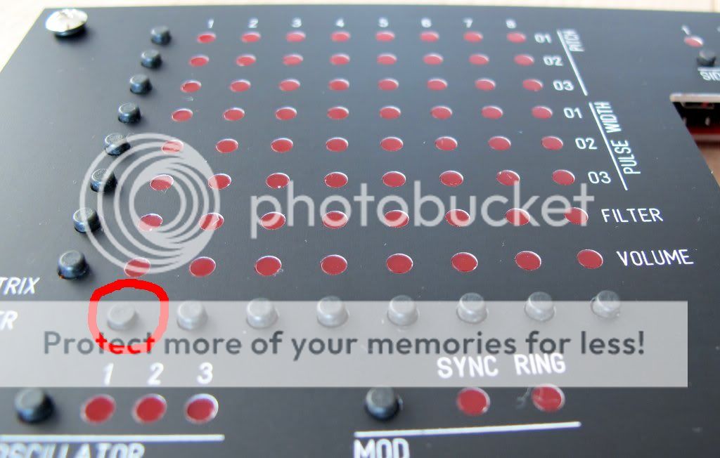
* Connect the “LED Loops” as shown in photo 8 - one encoder pin is always grounded - make sure you choose the right one. Connect the other end of the loop to your “supply voltage line”.
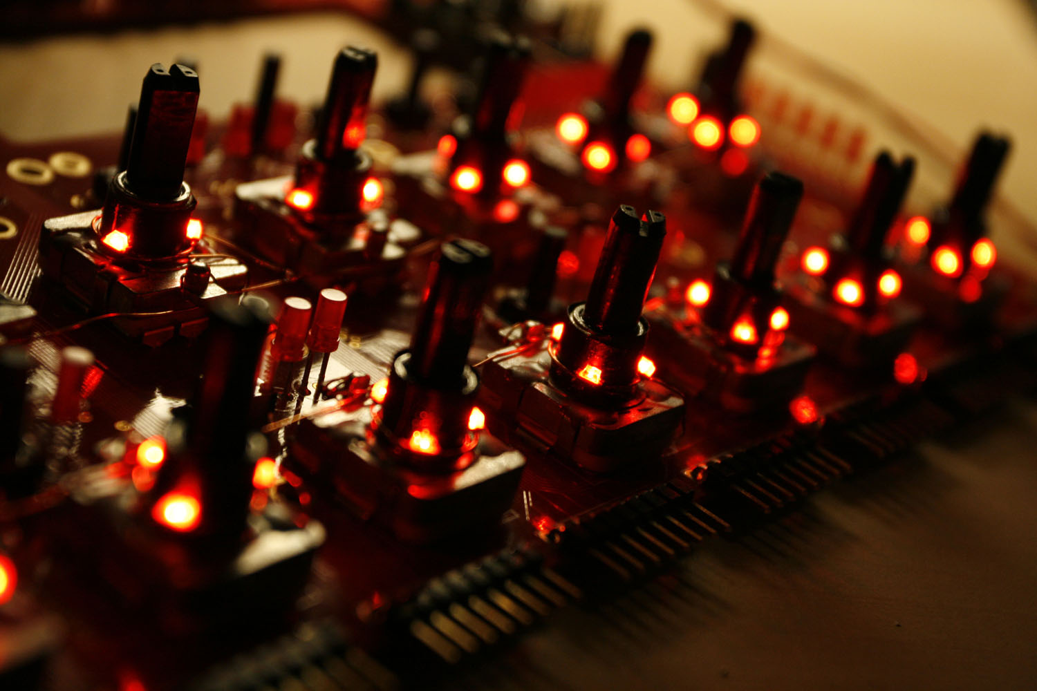
* The LEDs should be really close to the encoder axis, otherwise they won´t “shine through” the relatively small holes in the frontpanel. You can bend the wire to force them into positions, where they are most effective - very close to the axis and quite at the bottom of the shaft.
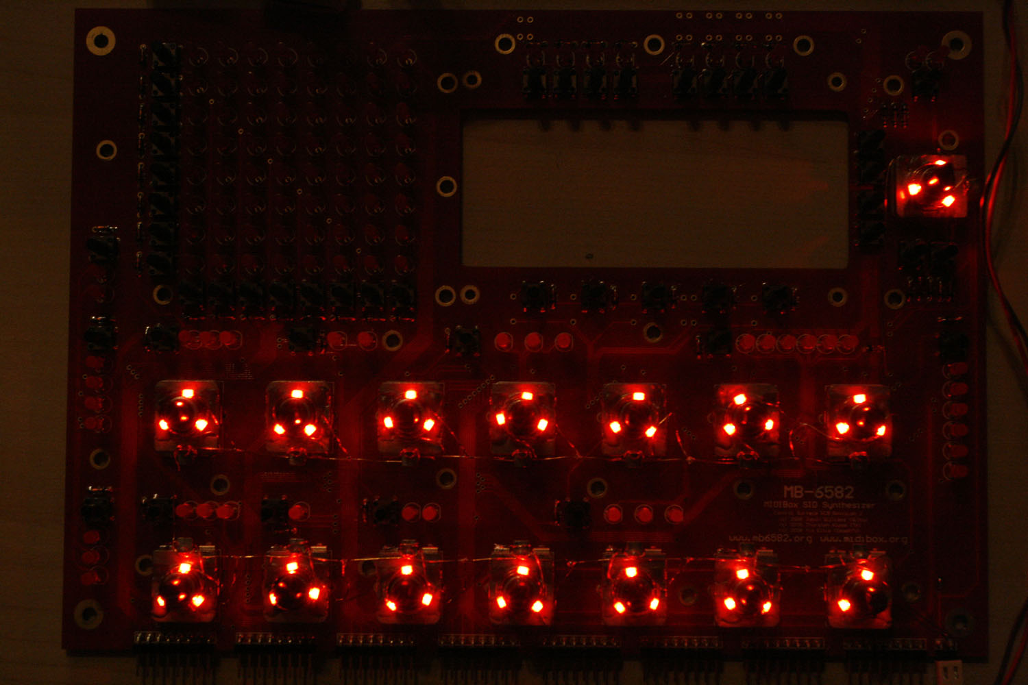
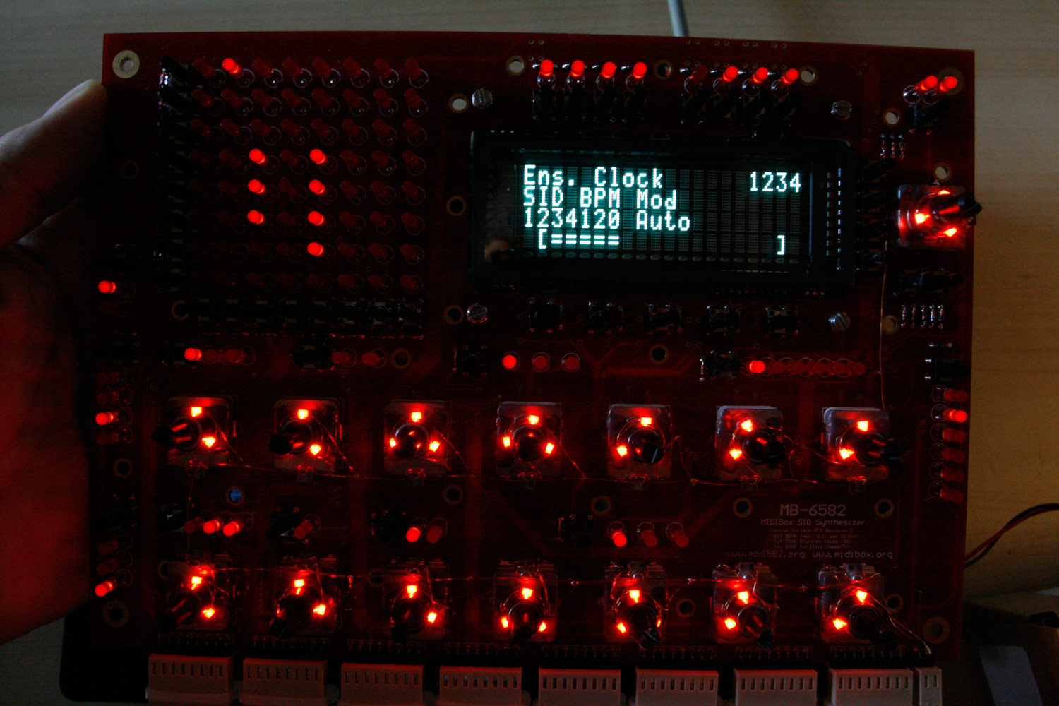
* When everything is ready your result could look like photos 9+10. Enjoy ![]()
Notes:
* A SMD caliper is highly recommended for this task. Best investment ever for SMD tasks :-).
* The SMD LEDs have markings for their negative pin, for example a color dot. Be sure to align all three LEDs in the ring in the same direction.
* It is not necessary to use a special SMD soldering tip - I used my standard 1.6mm flat tip which worked great.
* SMD LEDs burn quite quickly when you are careless with your soldering iron. Be sure to buy a few more than 45, because it is quite likely that you will lose some.
* My friend jojjelito just informed me, that the SMD work can be avoided in two ways:
a) use axial LEDs like these from digikey (lumex opto SSL-LXA228SGC) - they are a little bit more expensive but that will easily be compensated by the time saved.
b) use a transparent washer and glue LEDs to the side of it - you will obtain a nice area light. Nice tricks, thanks! ![]()
* Also, Wilba just used normal “through-hole” LEDs, that were connected to GND and a supply line and then bent very close to the axis.
* Lastly, Altitiude recommends using a LM317 + fixed resistor + trim potentiometer (look in the datasheet for a connection example) to be able to dim the backlight brightness. This is a very good idea, as it allows to adjust your LEDs to the optimum current draw.
Step 20: Upgrading to an awesome VFD ![]() (optional)
(optional)
Parts used:
* Noritake CU20045-UW5J VFD (Mouser 775-CU20045-UW5J)
* A dremel with a cutting wheel and a grinding/sanding tool
* Your favourite soldering equipment
Warnings :
* The described steps are suitable only for exactly the abovementioned VFD. I searched for many hours trying to find a VFD that fits into the MB6582 with relative ease without big modifications.
* The VFD also fits without altering the PCB with the dremel tool. But then you have to mount it a few millimeters deeper, and very slightly angled, which you may like or not - I wanted it to be as close as possible to the CS and be parallel to it.
* The current consumption of the VFD is quite high. In conjunction with the increased current consumption of the backlight LEDs, I would therefore highly recommend building an alternative PSU than the 25+ years old C64 power bricks in use. I will therefore post a small mini-tutorial of how to build a more powerful linear PSU later on. Even if this is not CS-specific, I feel, that it is an essential upgrade - there are reports of fried SIDs because of catastrophic 7805 voltage regulator failure. Frying the SIDs and the VFD would be bad. Very bad.
* Also, there may be a nice line of new 20x4 OLEDs suitable for your MB6582, if you want to avoid the high cost for a VFD.
* But the SIDs are old-school. So a VFD it must be… here we go :-).
http://discourse.midibox.org/t/topic/15481
Description:
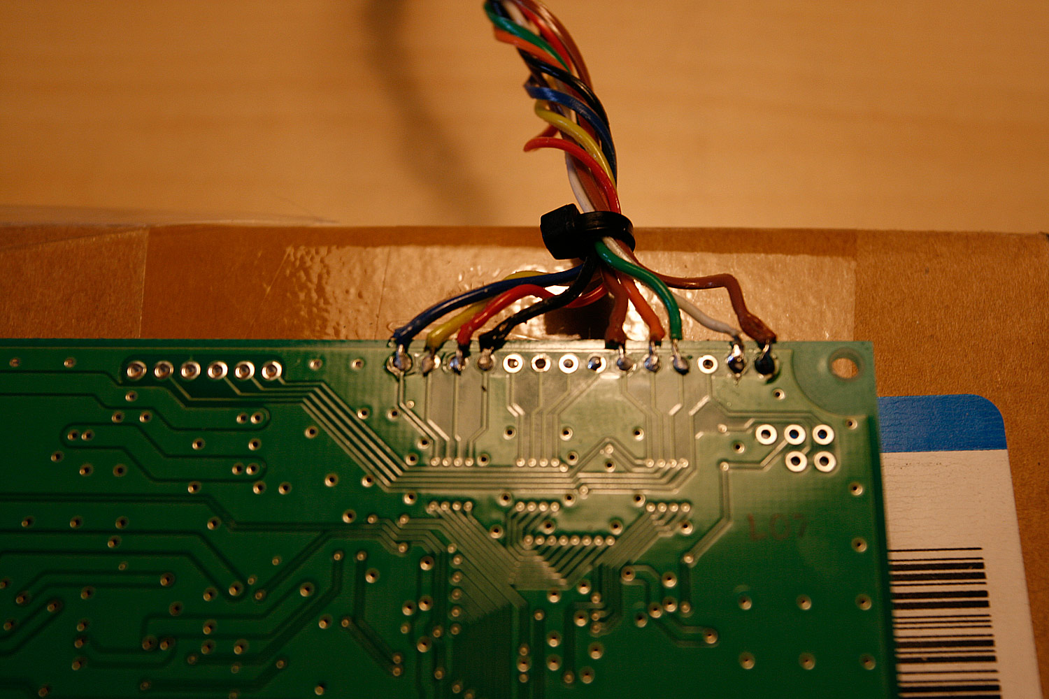
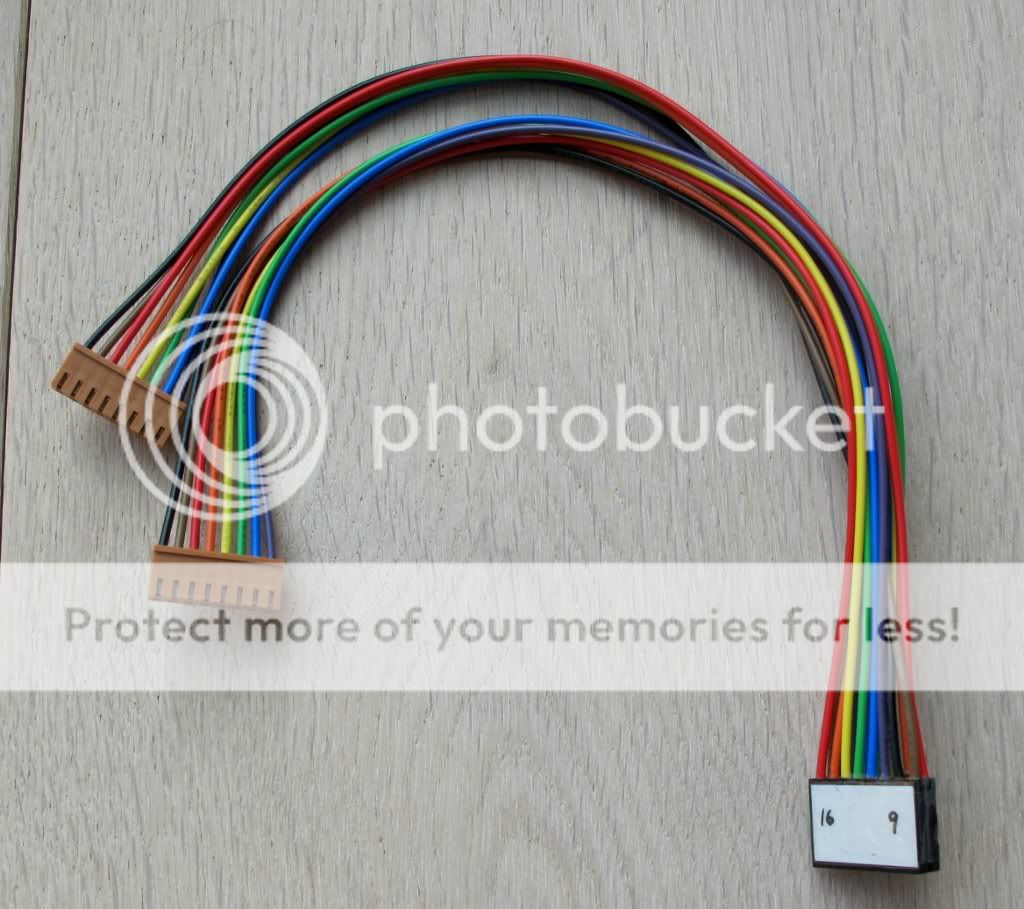
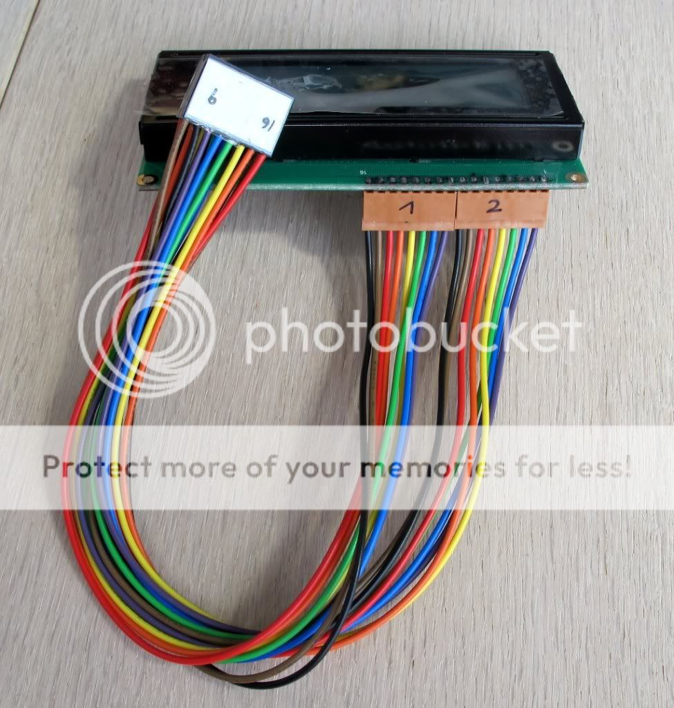
* The VFD is wired exactly like the LCDs. Just “copy” the pins and you are fine. Note, that I´ve left out the data pins 1-4, as the MB6582 uses 4-bit mode by default and the wires are not necessary (photo 1).
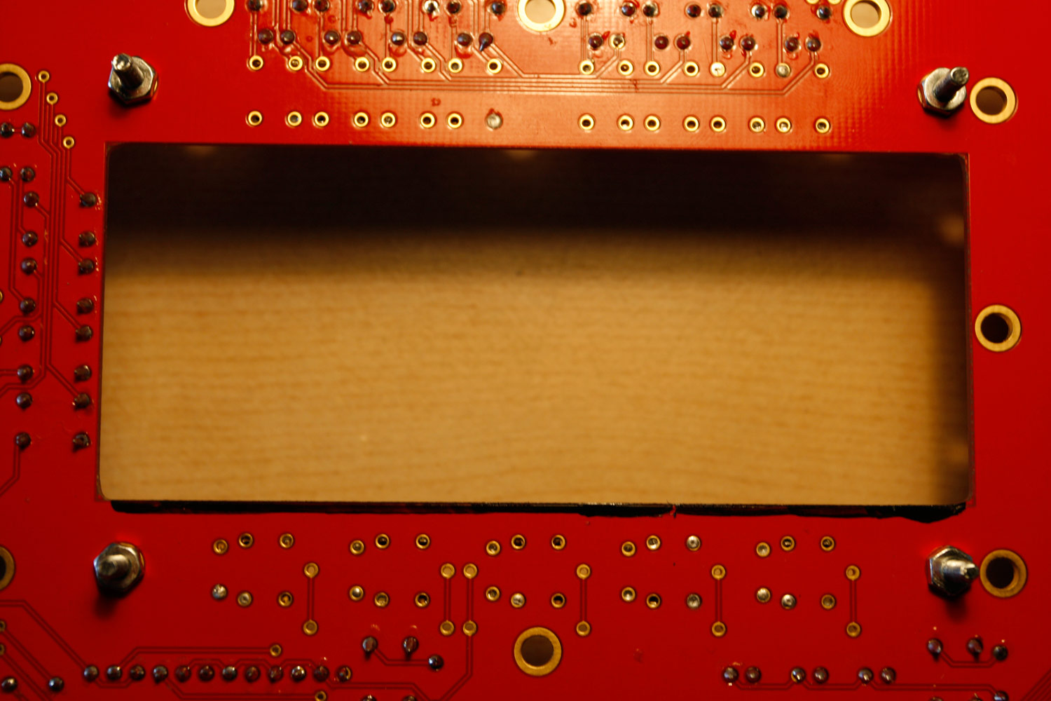
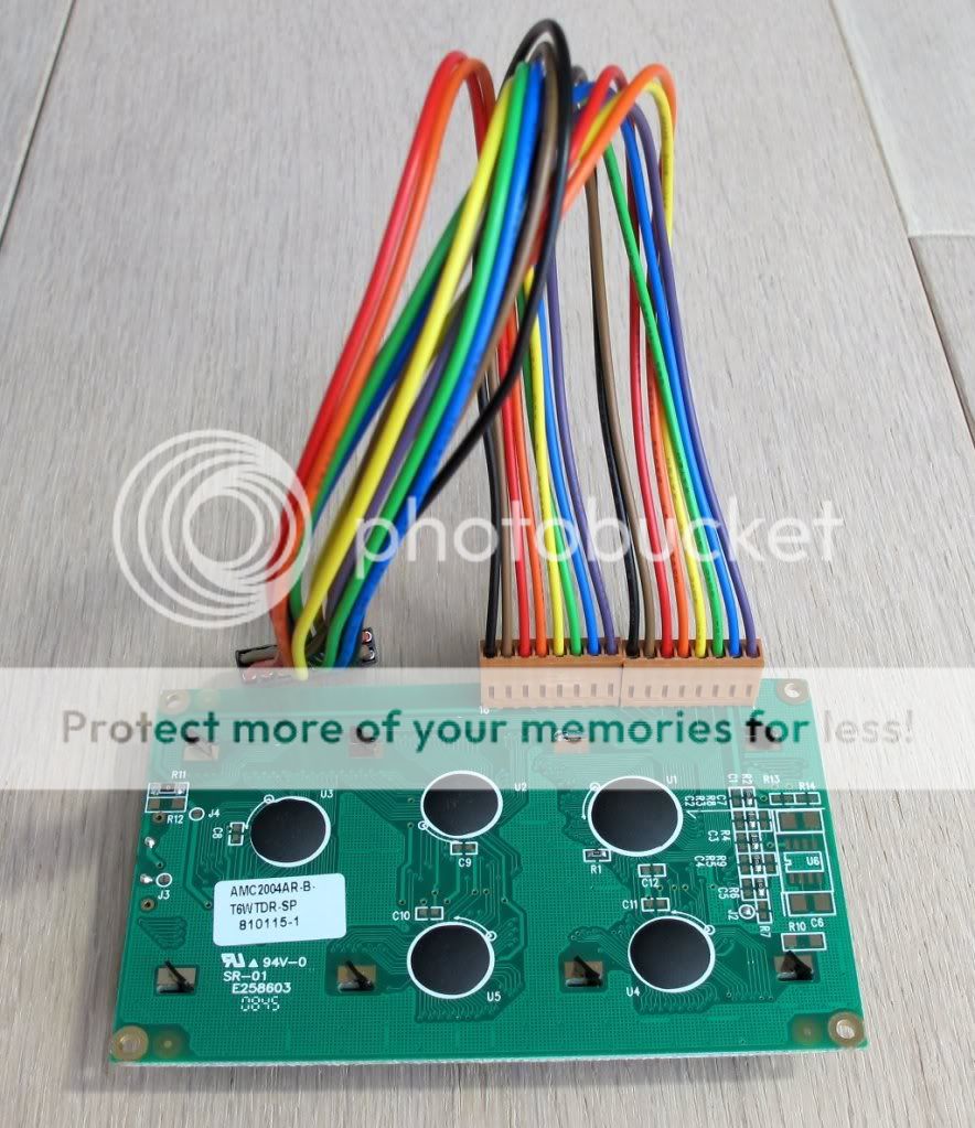
* As the VFD has some angluar pins just where the lower PCB display border is, you can take away ca 1-2 millimeters of the PCB with the dremel tool and a cutting wheel - there are no connections here, so no harm is done (photos 2 and 3).
* Also, the VFD has a “coil” very close to one tactile switch. As only the upper section of the switch is used on the PCB, you can use the dremel with a ca 10mm “grinding tool” to take out that section (photos 4 and 5). Be careful to not harm the switch case though. Also make sure that the two shortened switch pins do not contact the exposed upper or lower copper layers of the PCB.
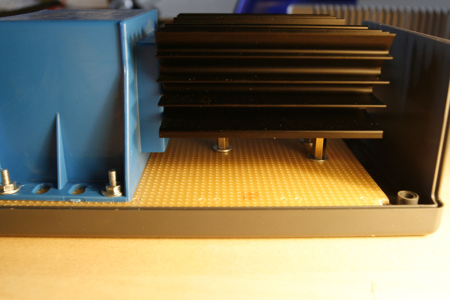
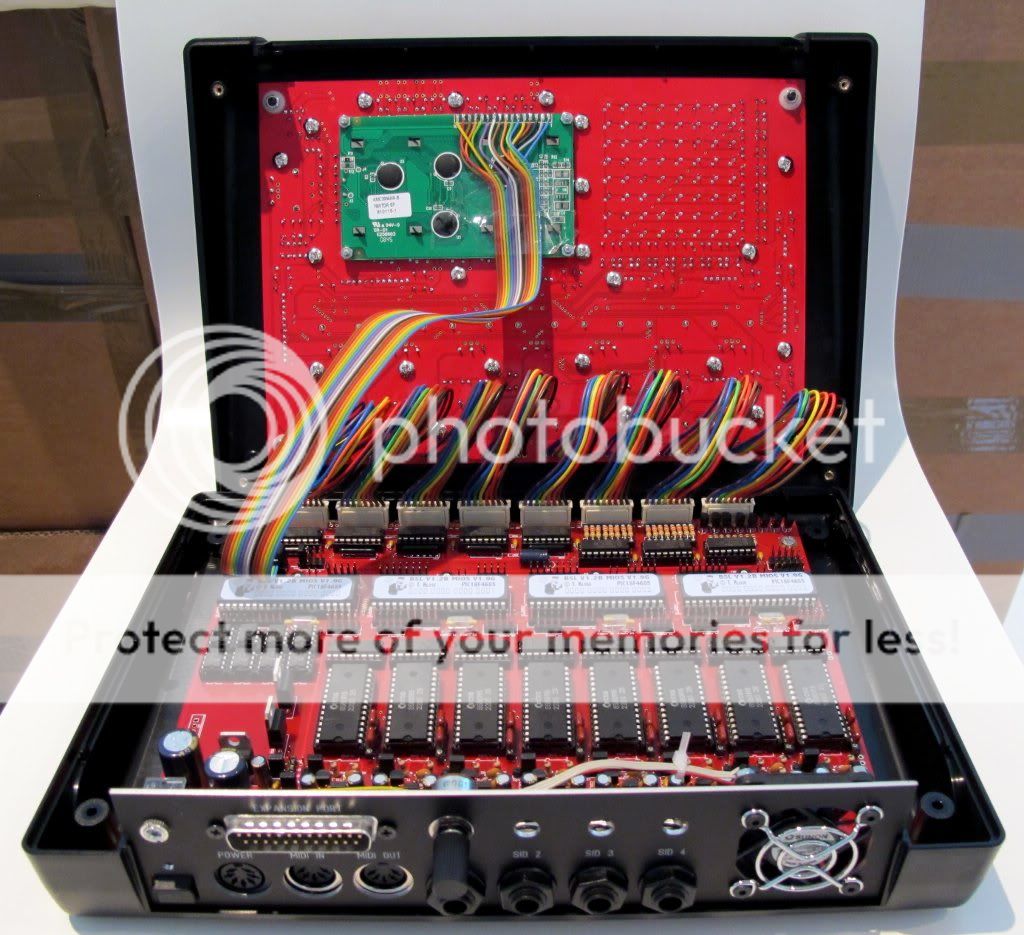
* Insert the M2.5 screws to which you add a M2.5 nut from above into the four “display holes” on the CS PCB. Fasten these screws with M2.5 nuts from below the CS PCB. These also serve as a 1.5-2mm spacer between the VFD and the CS PCB backside. Now stack your display from below and fasten it with four more M2.5 screws. Perform a fitting test - no parts should touch when the screws are fastened - it is especially important to control the “coil” area (photo 6) and the region where you soldered the display connection pins. In case of doubt, use insulating tape to mask.
* If you are really confident that all is right, connect all control surface connections and the display to the base PCB and turn it on. Make sure, that all LEDs, tactile switches and rotary encoders are working (photo 7).
* Now assemble the CS PCB and the upper part of the PT-10. If you are using flat-head LEDs, take care that you do not apply force, otherwise they will bend. Check for any LEDs that will not 100% fit their holes, unassemble and bend them lightly in the appropriate direction. When it is done properly, at some point, the two parts will just “click” together. Fasten all screws and for sanity reasons use masking tape to “protect” the display pin area from unwanted contacts (photo 8).
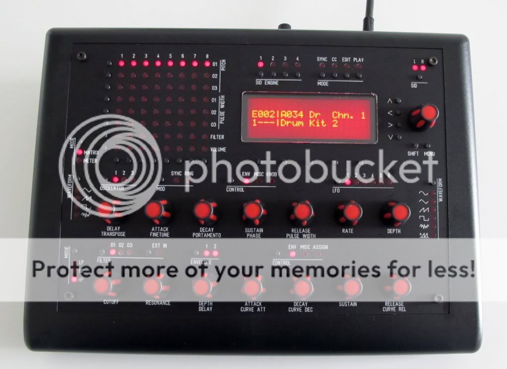
* When all is done, enjoy your new VFD (photo 9). I don´t yet own a plexiglass screen to protect it. Will keep you posted when I got it - frontplaten.net will produce them and they also have transparent colors available - which is great for shifting the color hue of VFDs towards the wanted color - or just limiting the brightness (by using a cool grey transparent window).
Step 21: Installing a studio-compliant 6.3mm stereo socket (passive mixer)
Parts Used:
* Göldo J002G 1/4 inch/6.3mm gold stereo socket (Thomann audio store, for example)
* A length of wire and heat shrink tube
* A 12mm drill, a countersinking cutter will do nicely (“Senkbohrer” in german)
* A roll of electrical insulating tape
* Your favourite soldering equipment
Description:
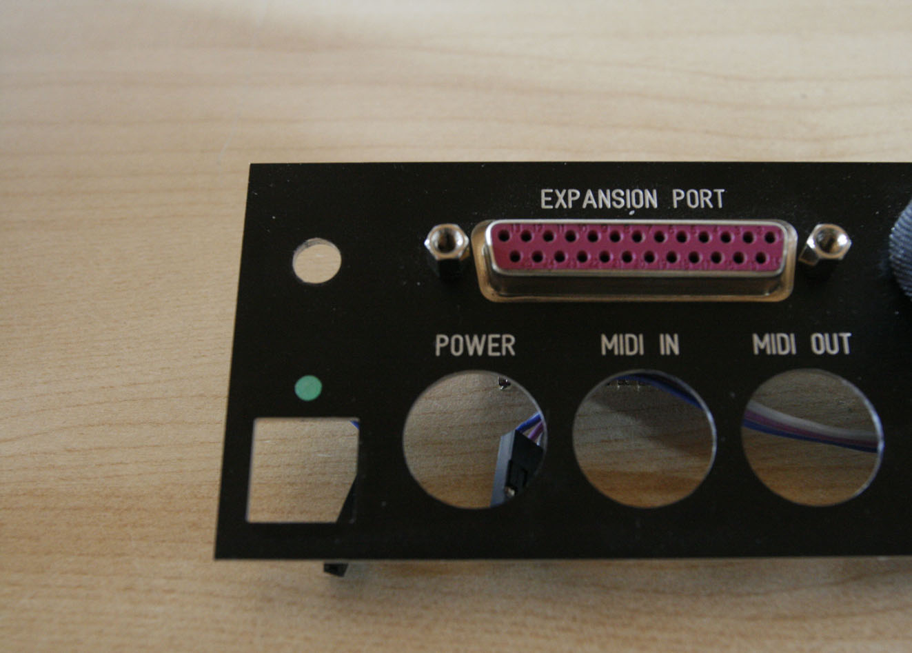
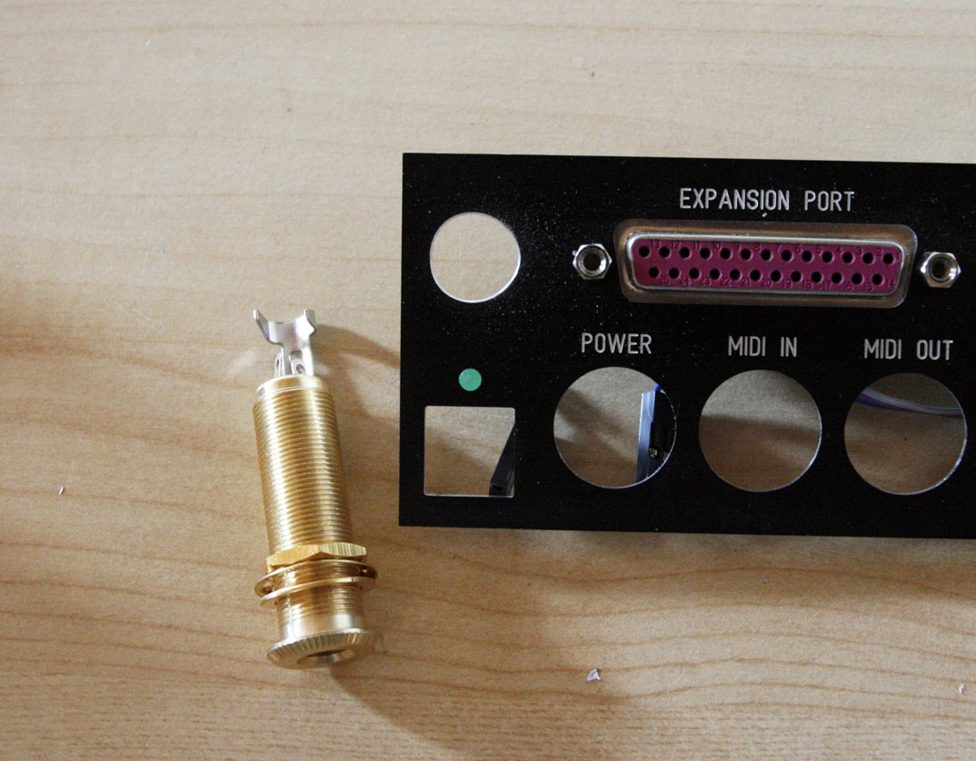
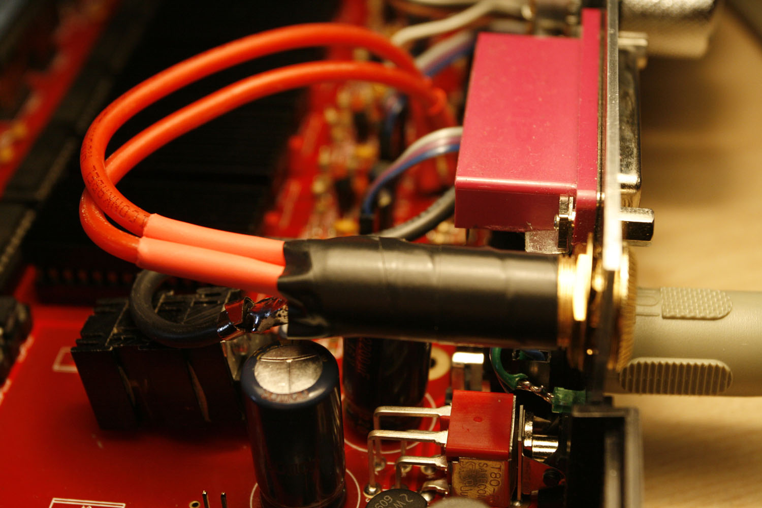
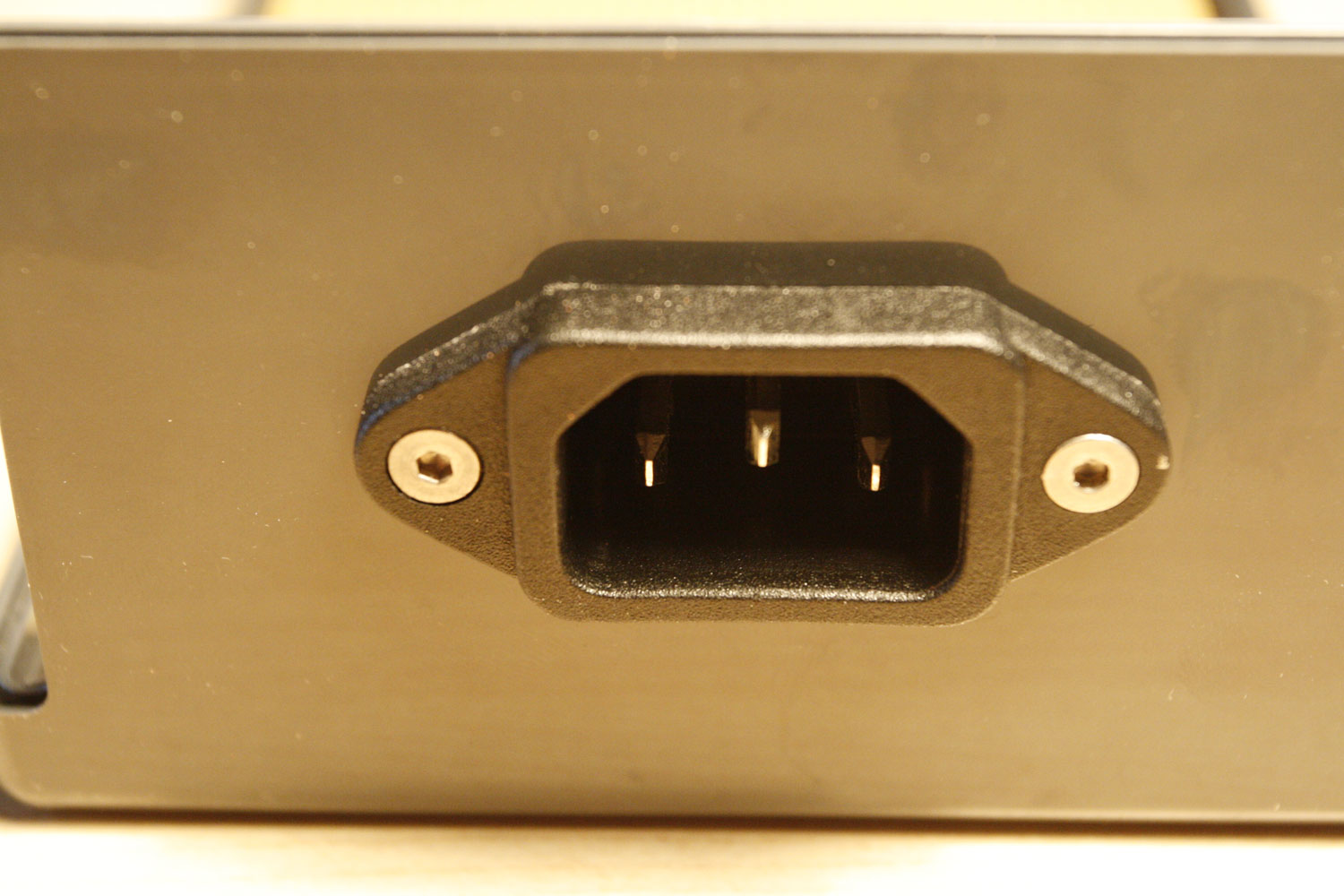
* First, extend the hole for the old 3.5mm socket to 12mm (photo 1 before modification and 2 after drilling).
* Install the stereo socket
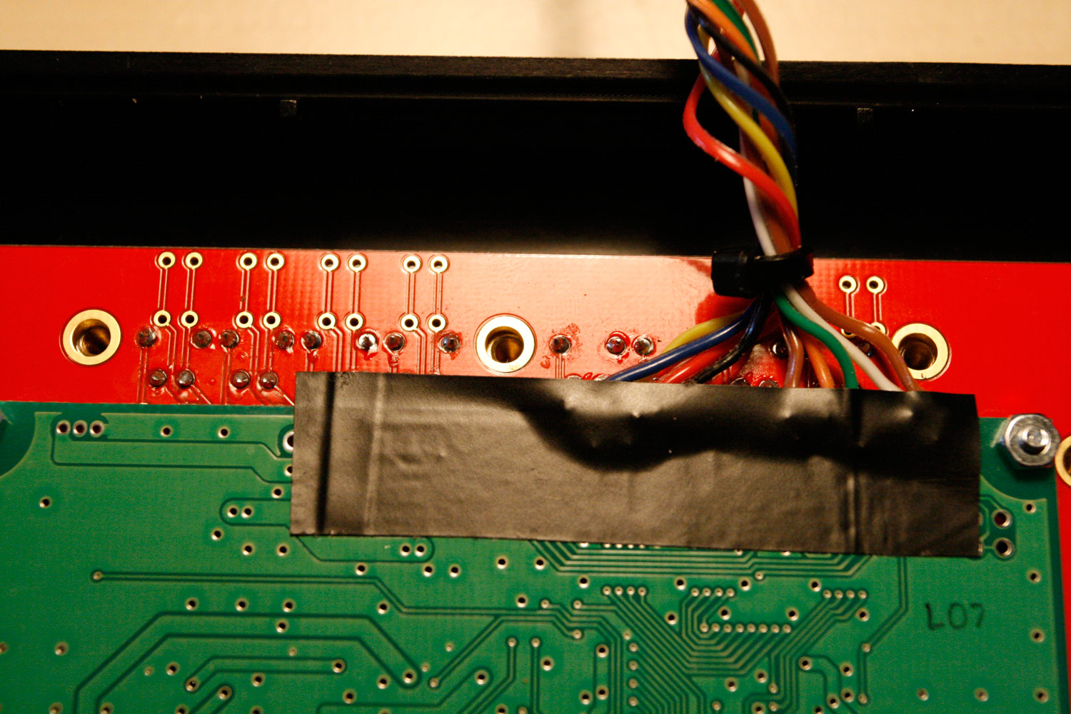
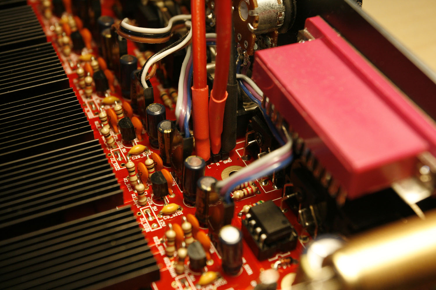
* Solder wires to the passive mixer audio-out headers - no plug is necessary in my opinion - protect pins by putting on some heat shrink tube (photo 3).
* Finally solder wires to the stereo socket, protect them with heat shrink tube and protect the whole socket with a layer of insulating tape (photo 4) for sanity reasons - the case closes nicely and neither the CS nor the display touches the new socket, so it is probably not necessary.
Enjoy your better studio connectivity ![]()
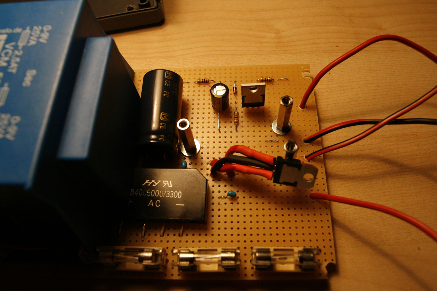
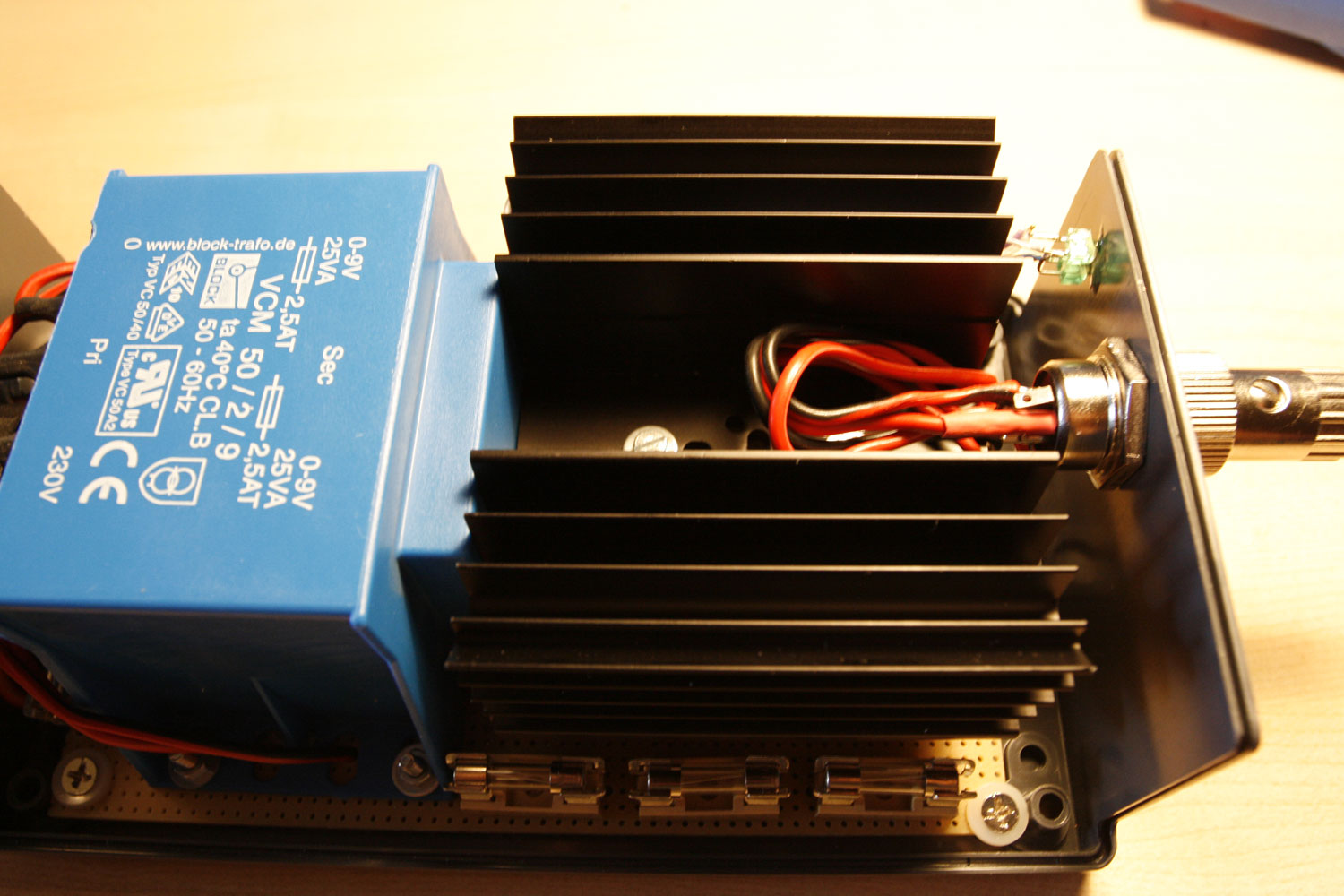
Step 22: Building a new protected linear PSU
Notes:
* Why upgrade from your old C64 PSU? Because it is old. And it contains an unprotected 20+ year old voltage regulator, that in a failure scenario will lead to a real mess - it will pump too high voltage through your MB6582, probably frying SIDs, your display and potentially the PICs. Not nice!
* On the other hand… working with high voltage and PSUs is really dangerous! Be extremely sure, that you know what you do. If you are not, you can always buy (rather expensive) linear PSUs commercially. Or you can go for a cheaper “switching” PSU, which may (or may not, the discussion is endless) introduce audible noise to your signal path. The costs for this PSU were less than 50€ and it is really nice:
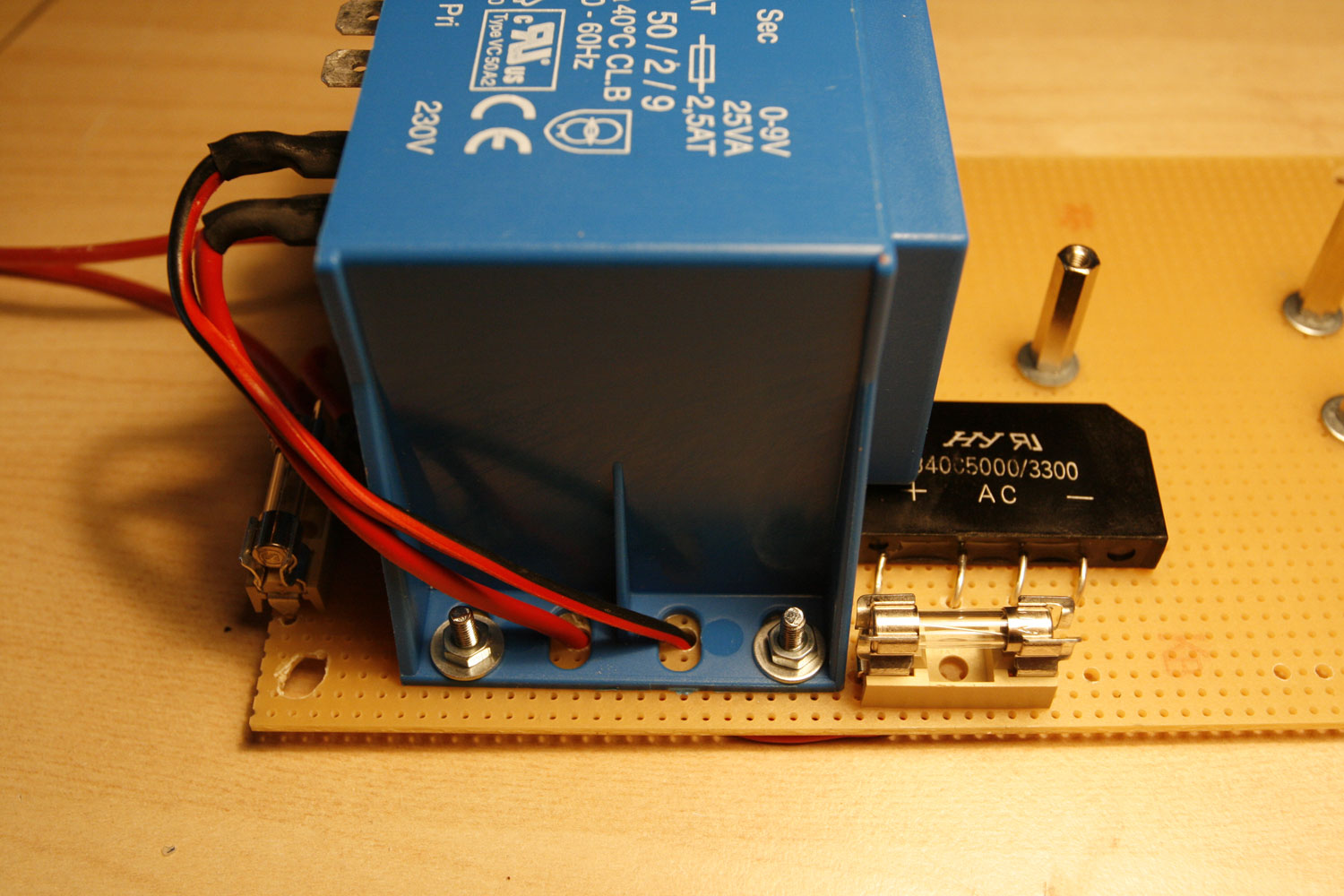
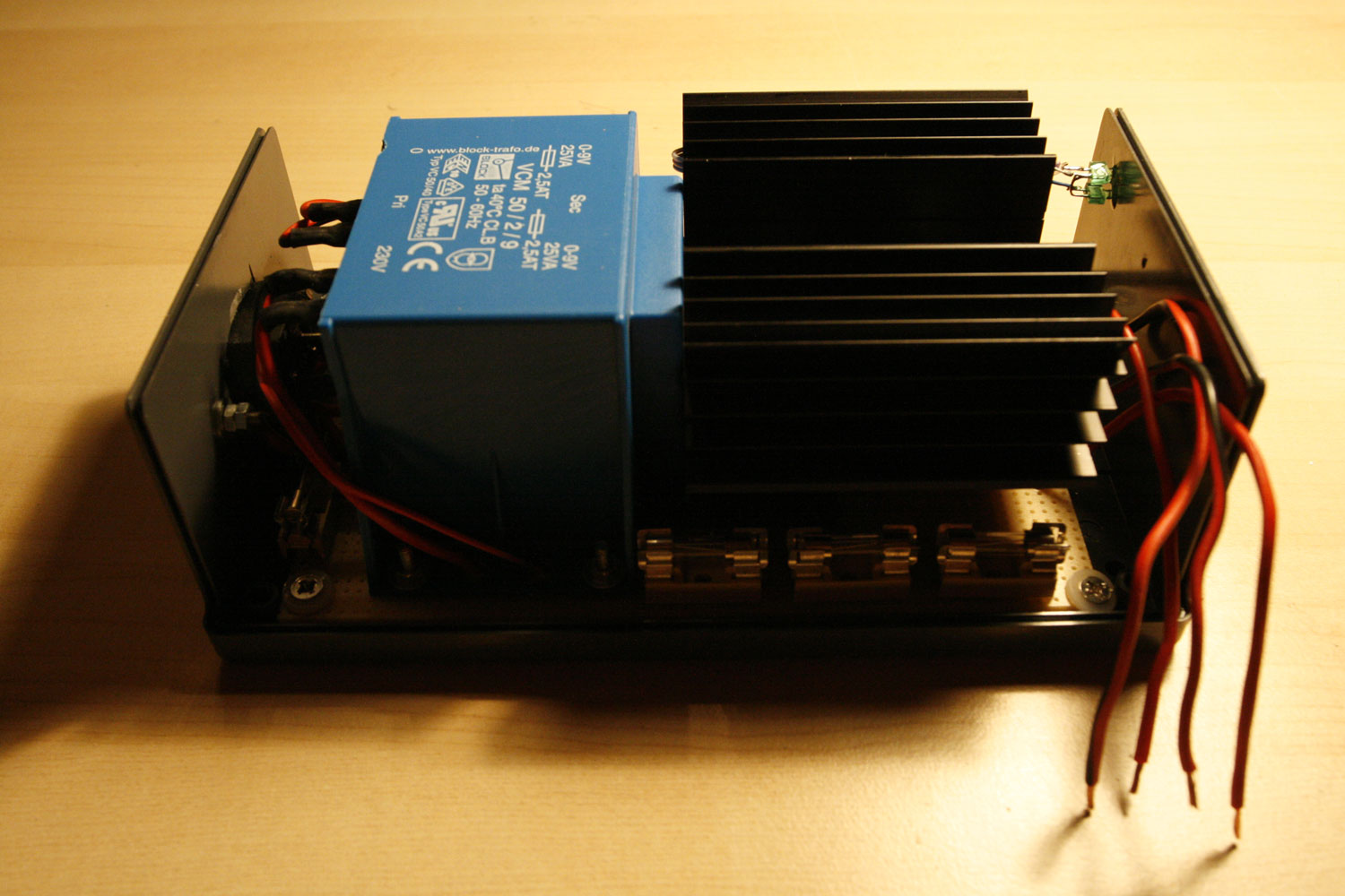
It contains a high-power 5V regulator (up to 2 Amps) and has more than enough power on the 9V rail (nearly 3 Amps).
It is fused to the max :-), with a total of four fuses in the PSU.
It also contains a “crowbar-protection circuit”. In case of a catastrophic VR failure (aka over voltage), a thrysistor will short circuit the 5V rail and blow a fuse.
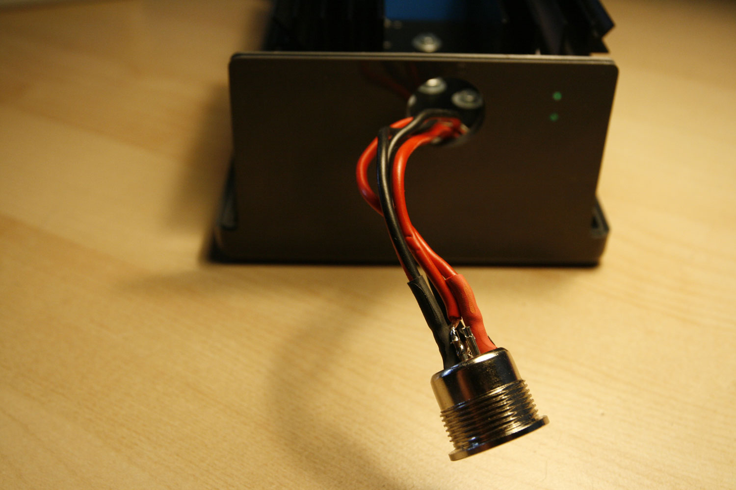
It contains LEDs for +5V and the active protection circuit.
It contains “long livable” capacitators - high temperature variants, that you would normally not get in “consumer hardware”.
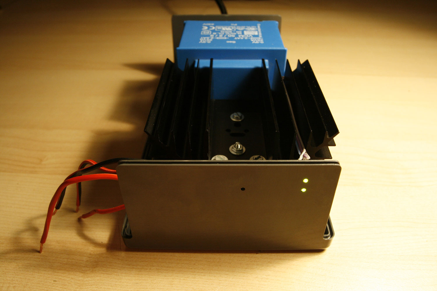
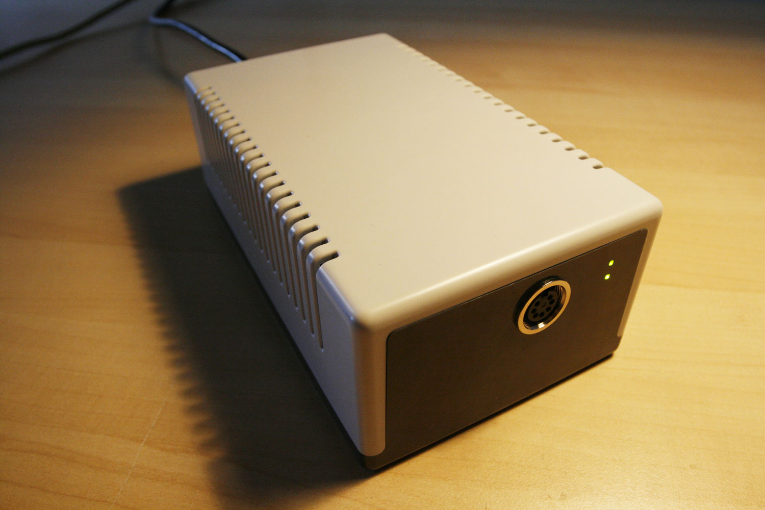
The case is nice and very sturdy.
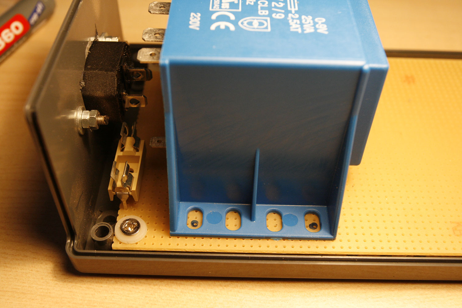
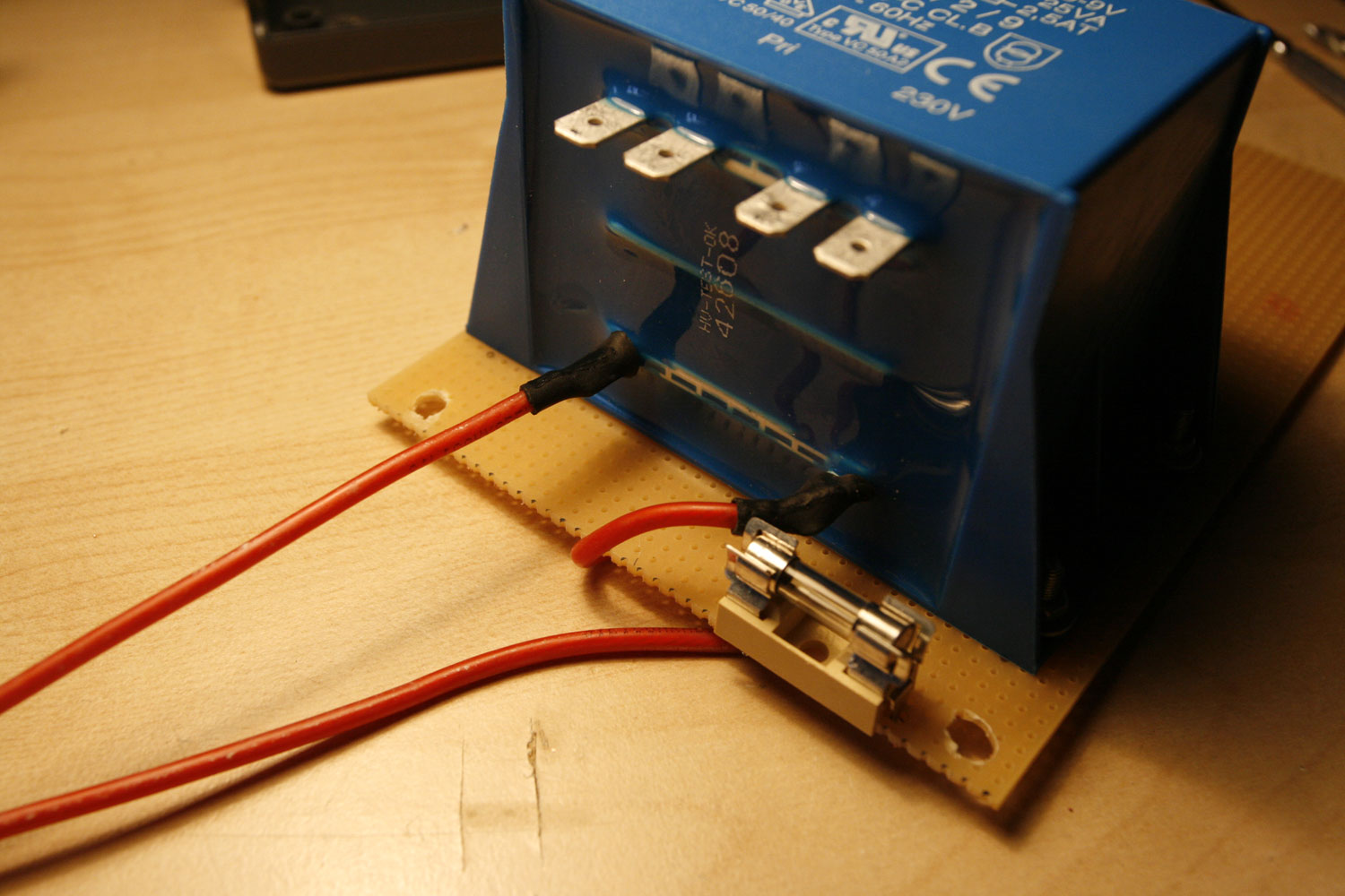
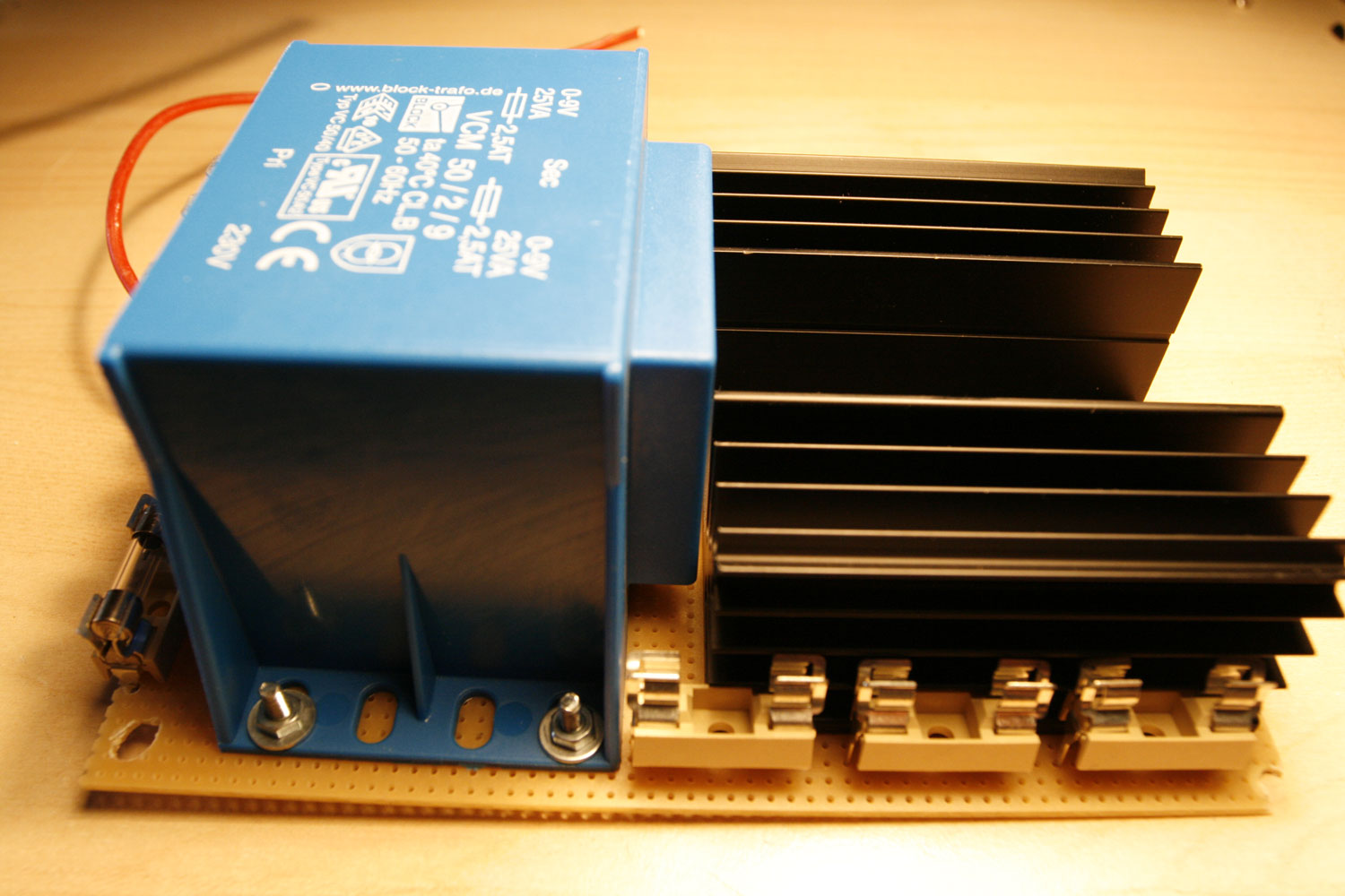
Description:
* This build is nearly identical to the description from retro-donald.de: http://www.retro-don…wernetzteil.php
* You can test the crowbar circuit (Picture 13) with a lab PSU - I did so. It triggers when 6.2V are reached (simulated catastrophic VR failure) and shorts the rail. Very nice :-). You could also create the crowbar circuit for the 5V rail as a standalone separate unit (with a fuse!) and reuse your old C64 PSU.
* I will not cover the build details this time, because of two reasons… first, you really need to know what you are doing - and second, I won´t take any responsibility for damages (to you or your environment) by reproducing the PSU. So please accept this as a mere picture gallery - no build description and part list this time!
Conclusion (II)
That´s it once again. Despite the CNCed plexiglass window screen, which I hope to obtain at some point in time, I cannot think of any other improvements to this fantastic synth.
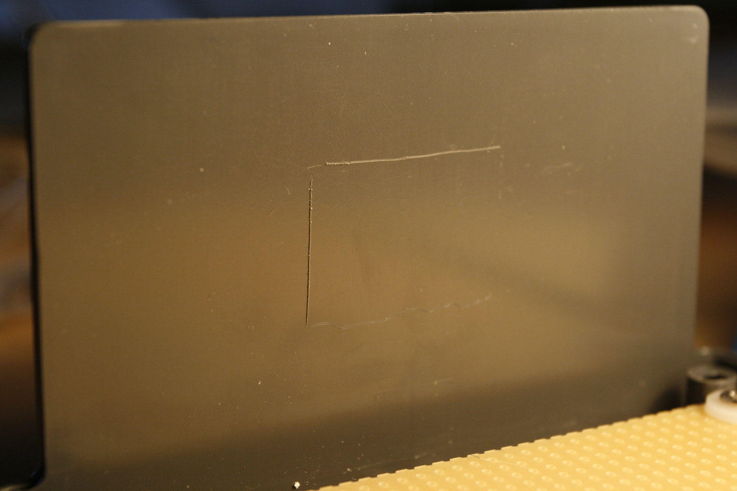
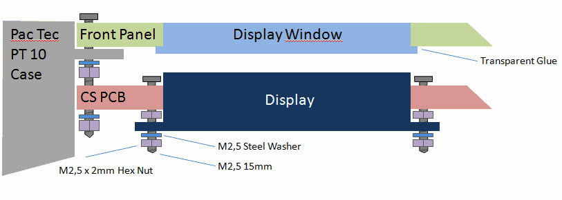
See image two for an overview of how a plexiglass window can be glued to the aluminum frontpanel from the backside. Thanks for the illustration, orange_hand!
Enjoy & I hope you found the tutorial extension useful.
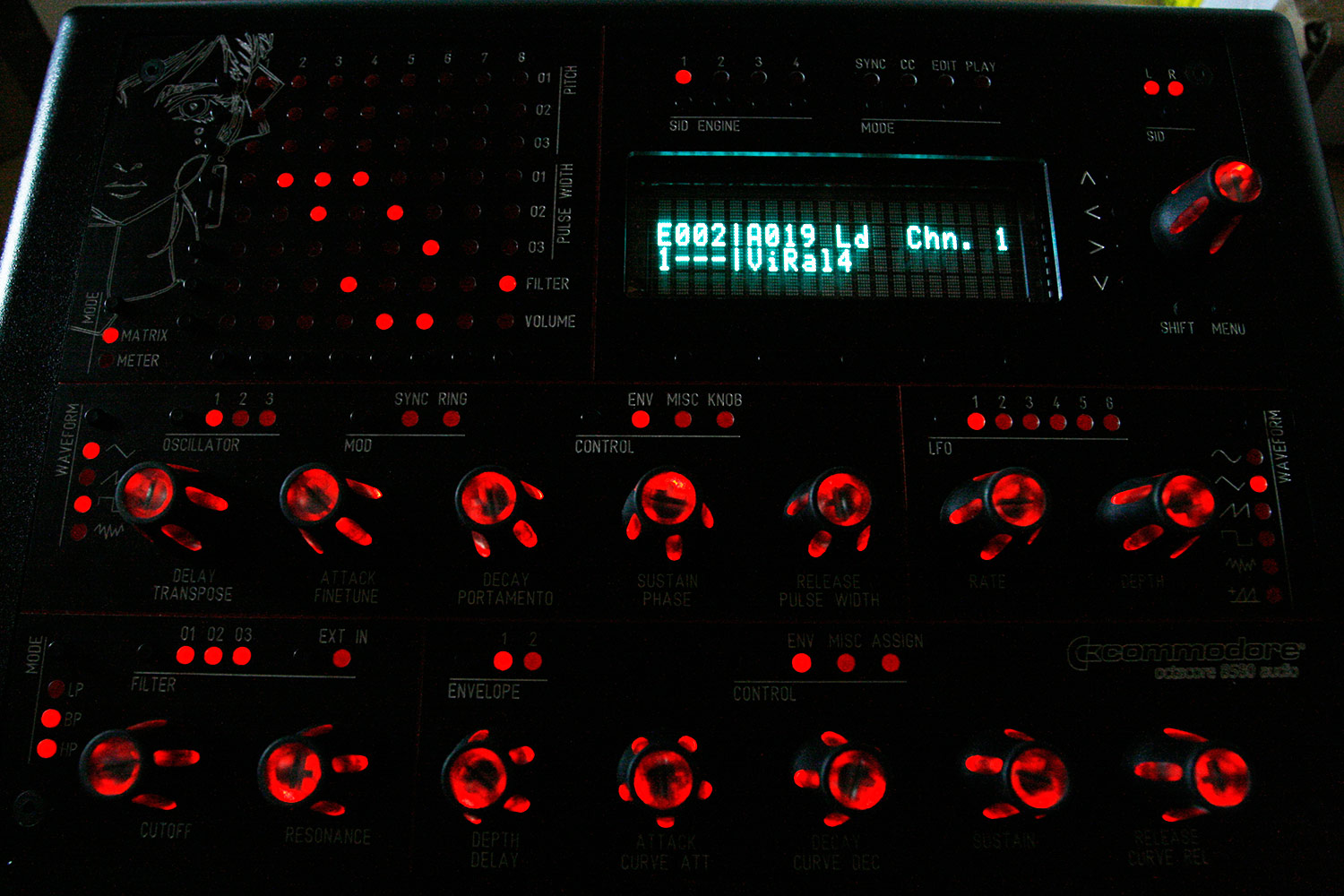
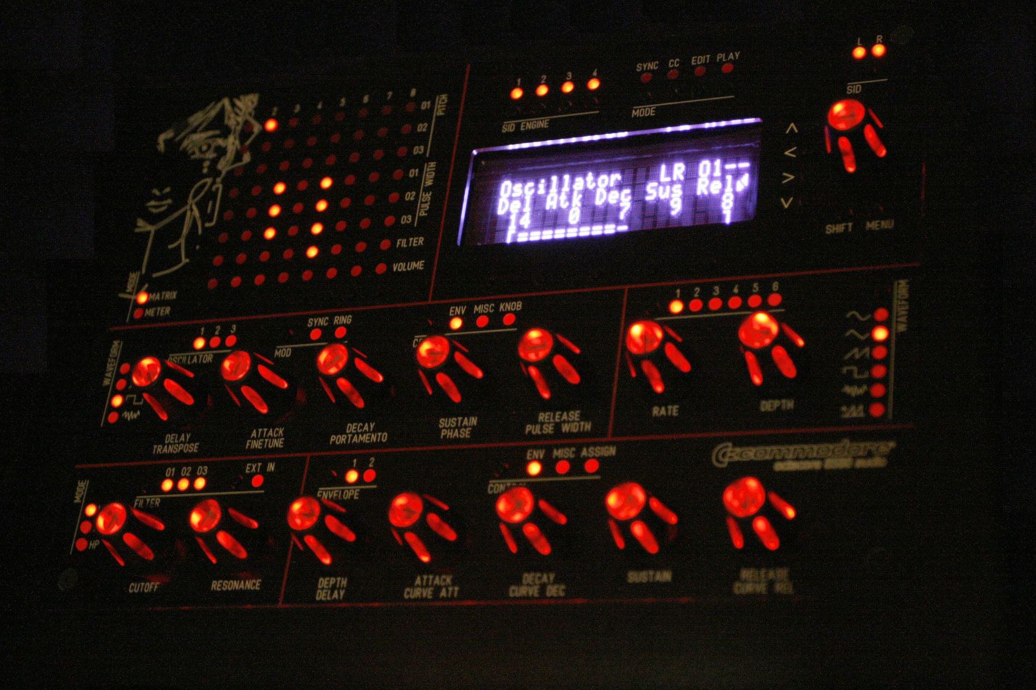
Edit: Added a night studio shot with purple/white VFD filtering, which I like the most right now ![]()
Best regards,
Peter
Just wow! That is an amazing machine inside and out, a literal work of art, extremely well done and congratulations. The tutorial is really well written too, humorous but very informative! I’d love to build a machine like this but I am a complete beginner so I think its out of my league for now. I’ve been looking at the sammichSID and I reckon I could do that. Hopefully there are some kits left, but as I am impatient for that gritty SID sound I’ve decided to build a basic stereo midibox. Do you know if there are any walkthroughs as clear as this for a noob like me? I’ve looked at the walkthroughs on the site and I think eveything is there, but its a little scattered and I’m not sure if I’ve missed anything. Have you written any more of these? I think I could build anything if you were explaining it! Anyhow, thanks for an entertaining read, Adam.
Thanks for your kind words, Adam. While I feel, that the MB6582 is a little bit advanced, by all means go for it, if you want it - it is not soo difficult, it just takes a little bit of time and you will get help, if you need it :-).
You can always start with a baseboard only, just put 2 SIDs in there and control it via Rutgers Java Editor first, then extend it with more SIDS and build the CS when you are fully hooked on the SID sound ![]() You won´t regret it, it is the best DIY build I had in my life yet
You won´t regret it, it is the best DIY build I had in my life yet ![]() .
.
Greetz, Peter
Hi Guys,
first of all I would like to thank Hawkeye for the great tutorial. I can say that this was one of the great motivation factors to build the MB6582. I haven’t done everything as stated in his tutorial and I think it makes sense to share some of my experience with the community.
I used the following custom made acrylic windows for the display. I think a window to cover and protect the display gives the box an additional professional finish.
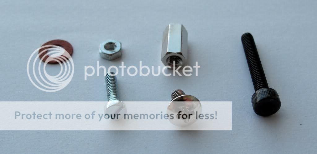
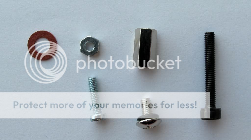
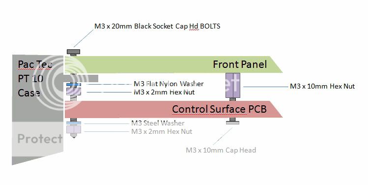
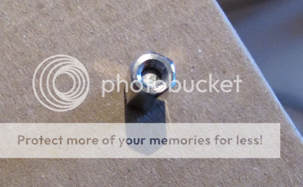
I have used a slightly different set of screws. To fix the control surface PCB to the front panel I used the screws with the black rubber washers. I also used different screws to fix the front panel as the hole was not drilled for countersunk screws.
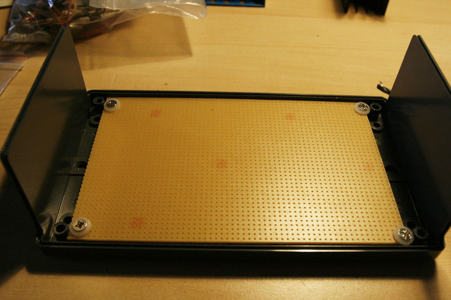
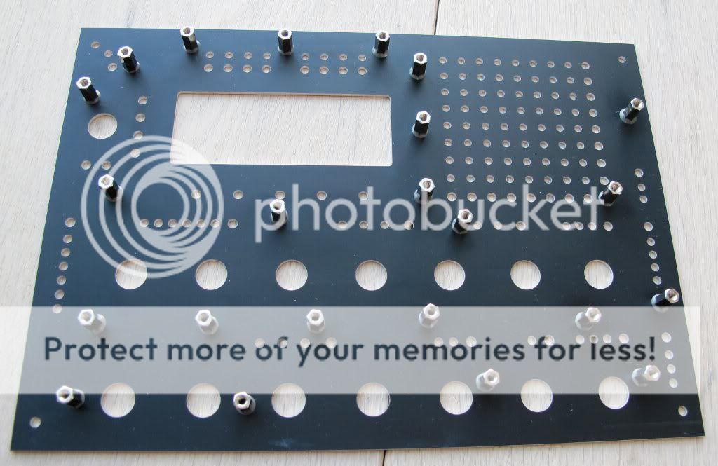
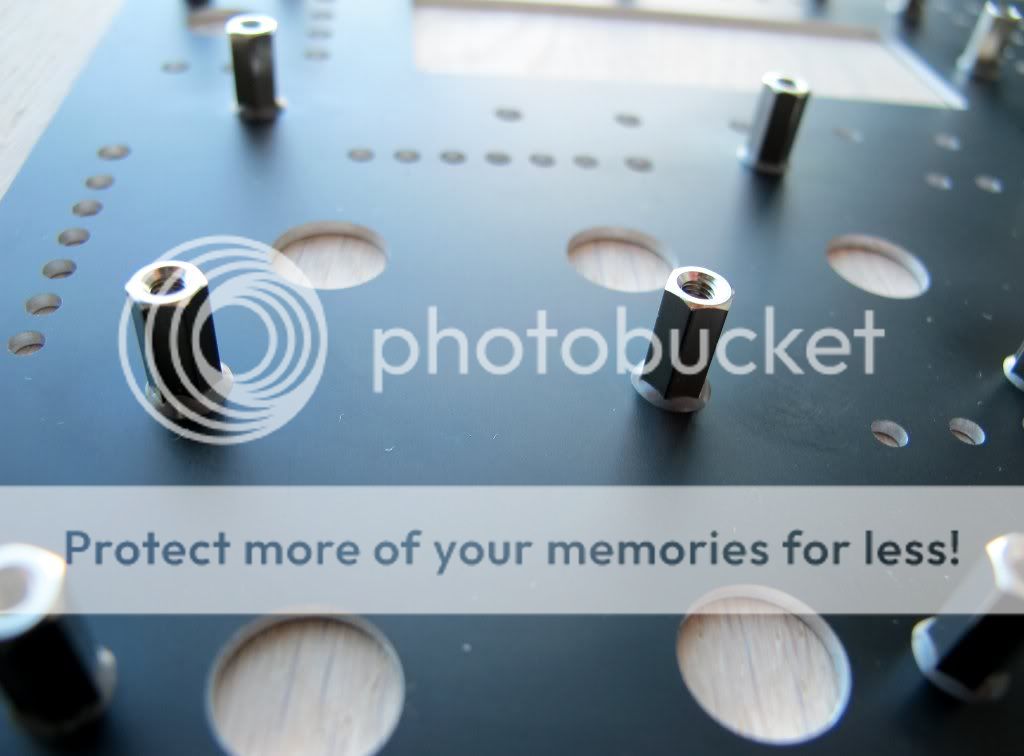
Here I have attached a picture how I fixed my front panel and the control surface pcb:
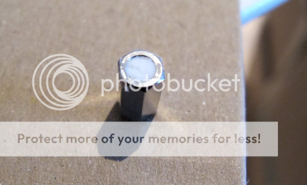
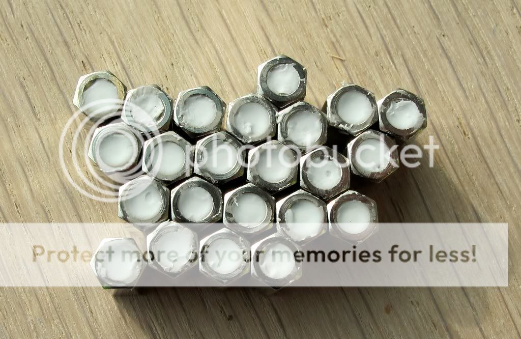
As I haven’t had hot glue and I didn’t want to use my preferred gum, I have filled the hex nuts with silicone which worked fine.
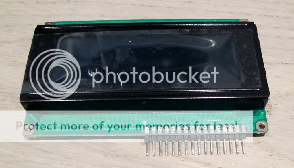
While I was waiting for some additional parts I tried different variations to connect the display to the base board. They all worked great but unfortunately they took to much space, so that I would not recommend these variations:
Here are some pictures of my power LED:
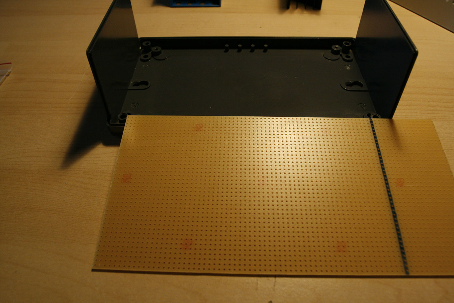
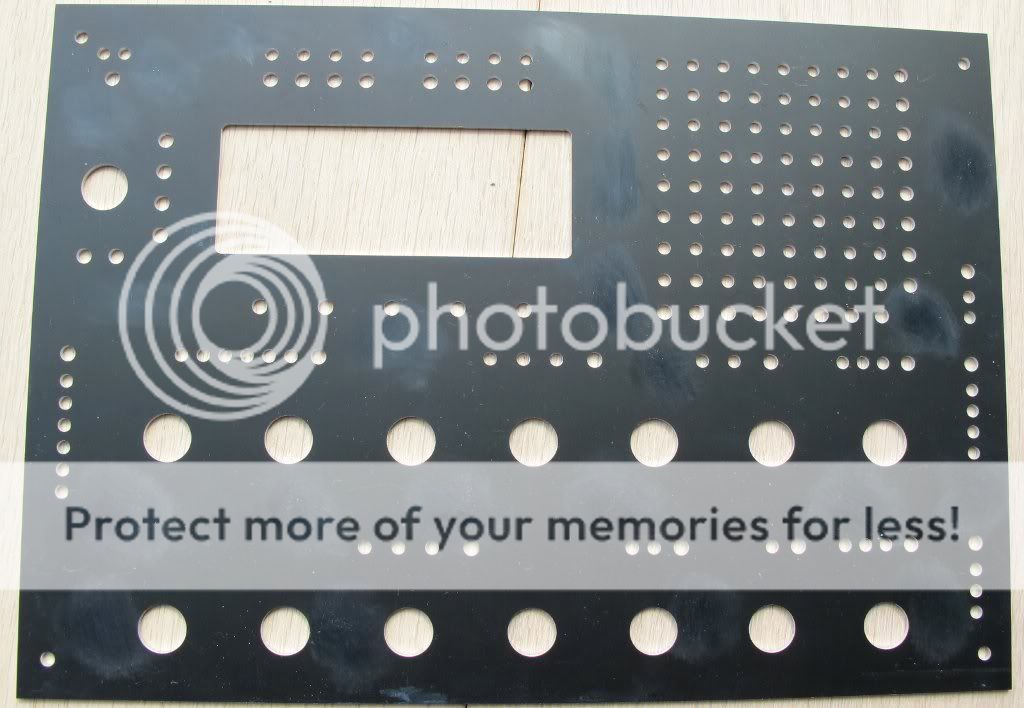
Here you can see the preparation of the front panel. I have used sand paper as recommended to prepare the spots where the hex nuts will be glued on:
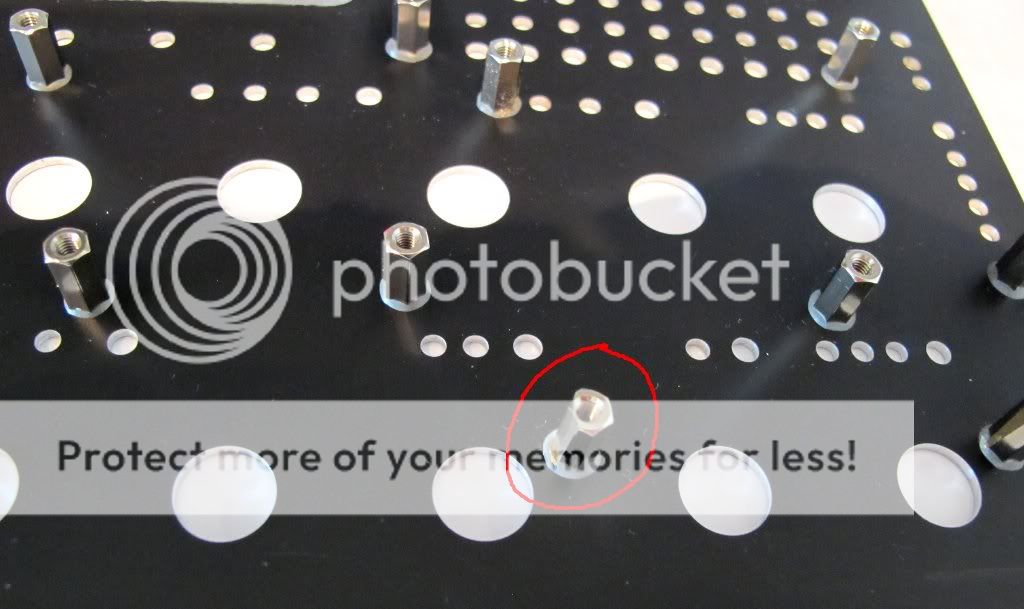
When I finally tried to install the encoders I figured out that there is one hex nut which is too close to the encoder. The front panel wouldn’t fit, so I decided to file some material off from the hex nut. When I did that I expected to break off the hex nut, but then I realized that the JD Weld is so terribly strong.
Finally the switches. I have realised that the Alps switches doesn’t have the same quality. There are some with a lose shaft, others have a slightly shorter shaft. So I would recommend to check them before you solder them on the PCB. Especially when there is a row of switches where one or two are slightly smaller, you will see it immediately.
Here is a picture of my MB6582:
I still have to complete the additional 3 feedback pots, but I am not sure if I will go for the “audio in” option … Maybe 2 feedback pots and 2 audio in jacks…
I wish everybody good luck with the box, it is a great project.
Cheers
orange
Great pictures and build!
Greets, Peter
Thanks for the quick reply Hawkeye. As far as I can tell, the best thing for me to do is just give it a try, right? Keep up the good work!
Hi i’m new(to soldering/electronics)
i’ve gone over this all of last night and all day today. the high res photos you include is immensely helpful, not forgetting the detailed instructions, I can’t stop going back to read more; partially adhd and ocd but all in good fun. I never have had thought i would be soldering electronics. I can’t lie i feel cool. nerate, the community and resources here are the shit. thanks this tutorial fukin rocks. best out there i think.
cheers,
moon
Related to Step 22: Building a linear PSU
Update:
The new PSU had - depending on week day and weather ![]() - some small noise issues… it was never really bad… but perceptible… like a 50hz hum and some infrequent “crackles”… I really wanted to solve the problem and was wondering why the new PSU wasn´t better in terms of noise than the old PSU… it has quality components all over… so… back to the assembly table
- some small noise issues… it was never really bad… but perceptible… like a 50hz hum and some infrequent “crackles”… I really wanted to solve the problem and was wondering why the new PSU wasn´t better in terms of noise than the old PSU… it has quality components all over… so… back to the assembly table ![]()
After bugging Antix (because he built an identical PSU) and getting lots of feedback from orange_hand… the following tuning steps were performed…
a) Installation of a second 2200uF capacitator in parallel to the first one… which improves ripple filtering (thanks for that tip, Antix!).
b) Very close installation of the 100nF filtering capacitators to the 78S05 voltage regulator (you can directly solder them on the 78S05 pins, these capacitators are tiny) - this helped a lot… any connection longer than a few centimeters seems to act like an antenna and picks up transformer hum and switching psu noise from nearby synth switchers (thanks a lot for that tip, orange_hand!)
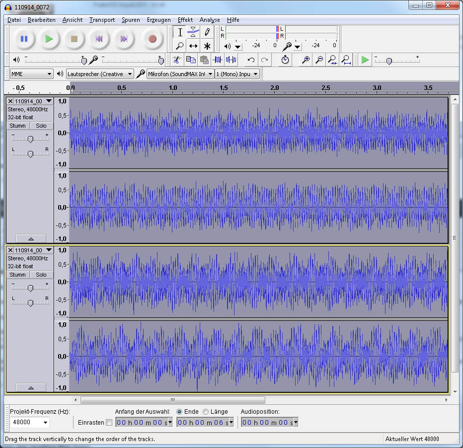
I did some A-B recording tests (using an old C64 PSU as a sparring partner) with the same unplayed patch (“silence” output from the MB6582 SID pair 1) at the same recording levels using max line-in gain on a tascam dr-100 audio recorder, recording 24bit, 48khz wavs…
And yes… there is a difference… see photo 1… after amplifying both waveforms once again with 45.5db in audacity, the lower waveform (old C64 “elephant foot” PSU) reached the maximum amplitude… the upper waveform (new linear PSU) was more silent (and has 2.5db more room to the amplitude max after amplification). It is a barely audible difference when using headphones during A-B tests, but every little bit of noise reduction counts… it is very well audible, when amplified… so… mission accomplished ![]() .
.
Apart from the improved protection of the SIDs, it might make sense to build such a PSU just because of the lower noise level.
Greets!
Peter
Congratulations Peter, this is pretty good news ![]() ! I am looking forward building the same PSU…
! I am looking forward building the same PSU…
Cheers
orange
hi guys,
here’s an alternative link to the flat red 3mm led’s.
I tried to order from reichert but they won’t ship to the u.s.
http://www.newark.com/jsp/search/productdetail.jsp?sku=26M0011
cheers.
Hi,
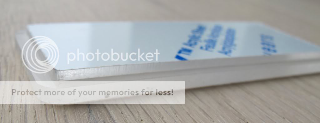
today I received my new MB6582 rear panel which was made by Schaeffer AG in Germany. I love the German quality work ![]()
As you can see it is still in its protective cover. You will recognise that I have modified the panel with some features:
I increased the hole for the mix out jack
The following descriptions were added: Mix Out, On/Off, MOD1-4, Audio Out, Fan
There is now a hole for a standard on/off switch for the fan, as well as an indicator LED for the fan
I also added the device name, the serial number of the box as well as the name of the builder ![]()
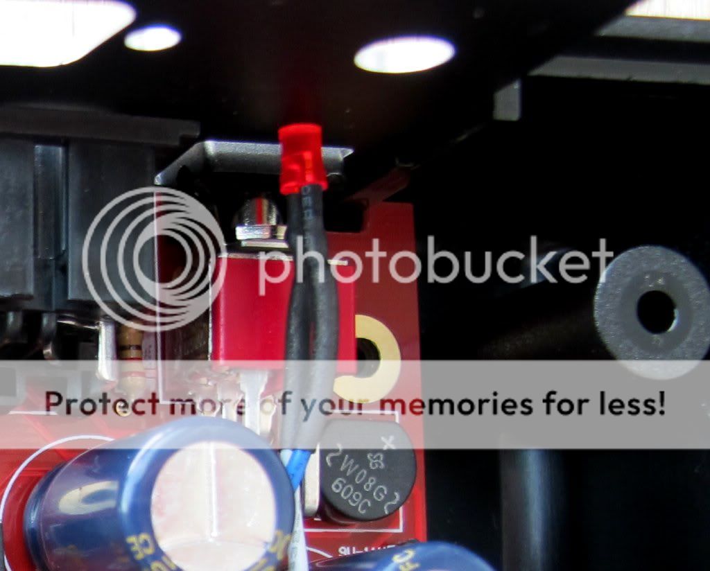
I connected the fan with the switch and the LED:
I connected a cable to the mix out jack:
Here you will see the completely assembled rear panel:
Here is the final rear panel (apart from the pot caps, which I haven’t installed so far):
I hope you also like the minor improvements…
Cheers
orange
That backpanel is a great upgrade! Cool to see someone also implementing that 6.3mm “mix audio out” jack… ![]()
Also, the fan switch is a very good idea!
Greets,
Peter